CAN COMMUNICATION SYSTEM
Figure 1. Bus 5 (LHD Models (Except Models with 5L-E Engine))
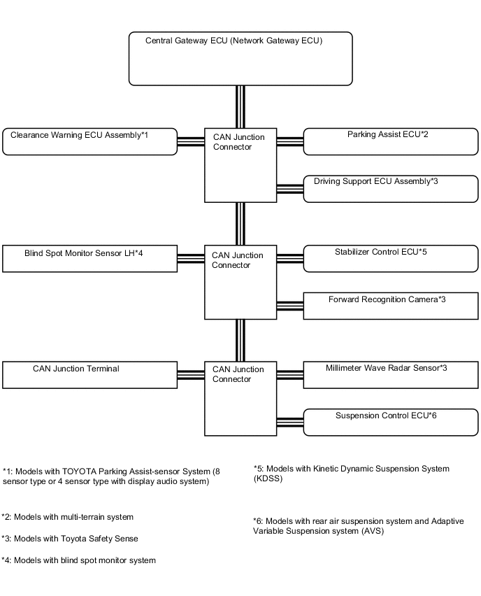
Figure 2. Bus 5 (RHD Models (Except Models with 5L-E Engine))
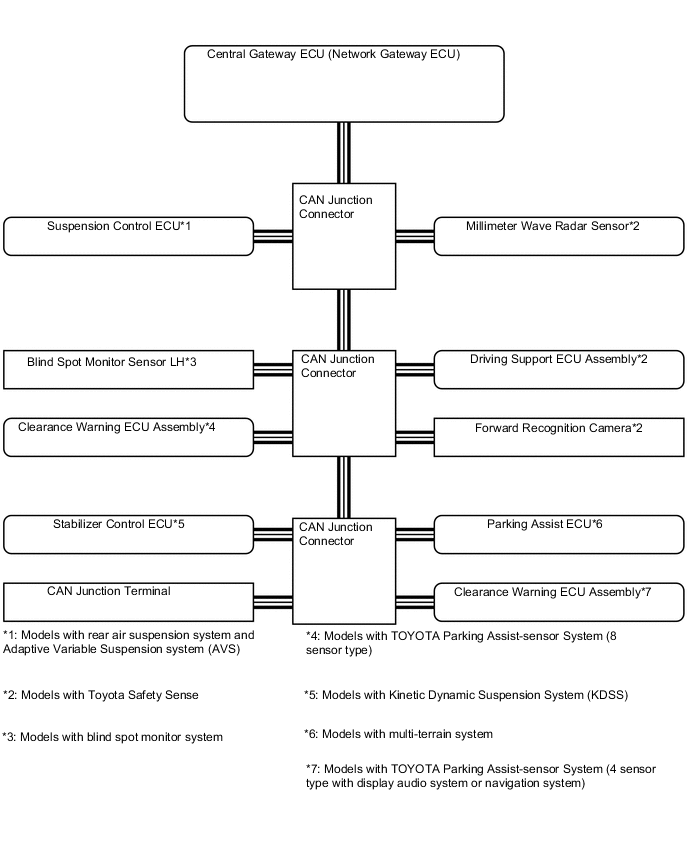
Figure 3. Bus 2 (LHD Models (Except Models with 5L-E Engine))
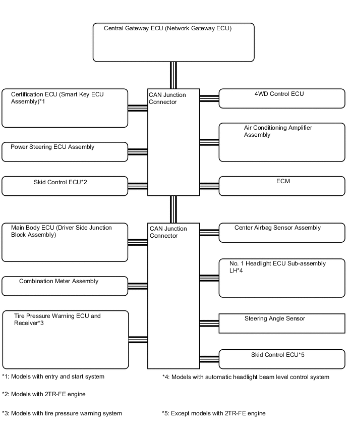
Figure 4. Bus 2 (RHD Models (Except Models with 5L-E Engine))
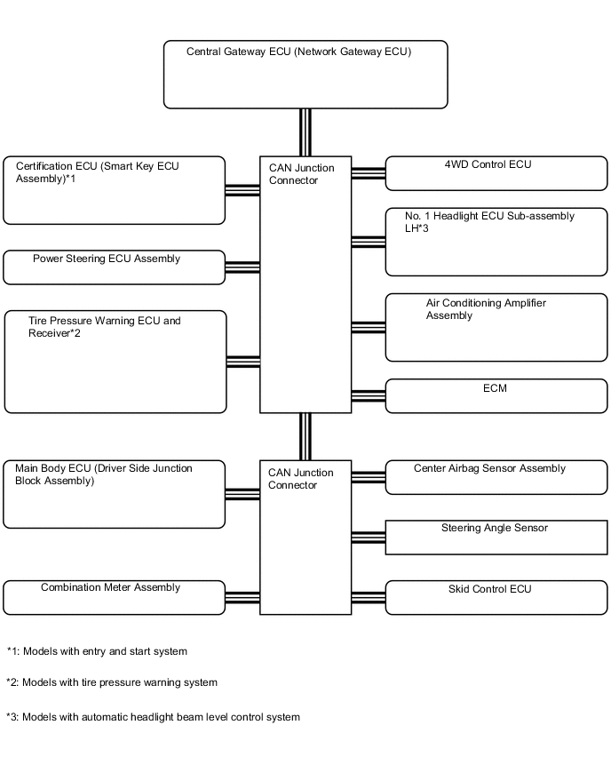
Figure 5. Sub Bus 1 (Except Models with 5L-E Engine)
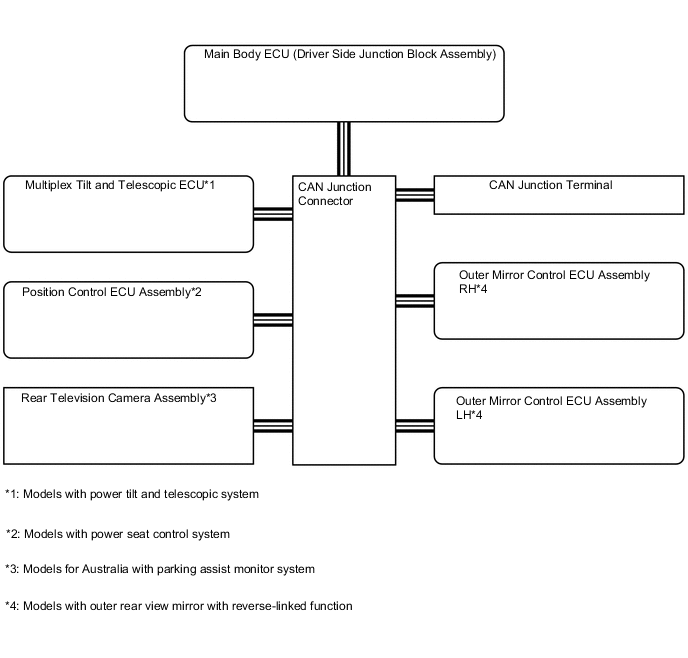
Figure 6. Bus 3 (Except Models with 5L-E Engine)
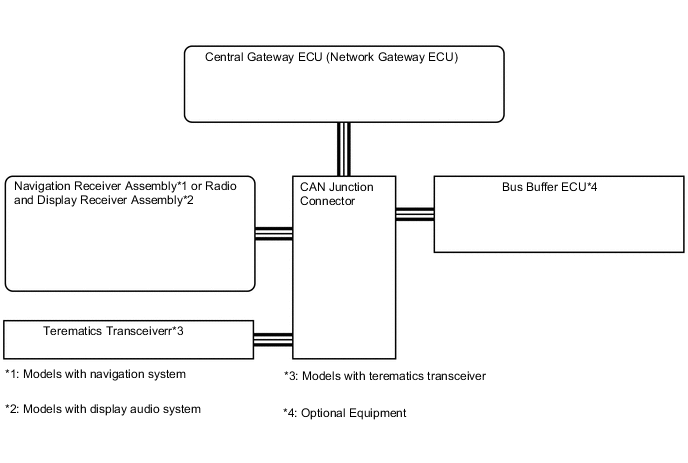
Figure 7. V Bus (Except Models with 5L-E Engine)
| *1 | Central Gateway ECU (Network Gateway ECU) |
Figure 8. LHD Models with 5L-E Engine
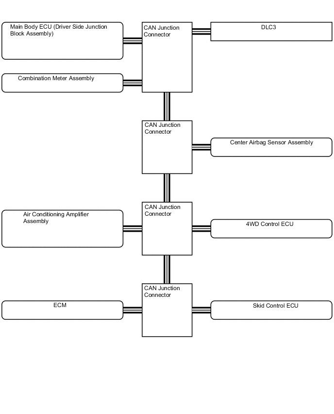
Figure 9. RHD Models with 5L-E Engine
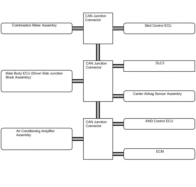
Figure 10. Powertrain Bus (Models with 1KD-FTV Engine with Automatic Transmission)
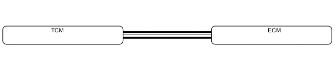
Figure 11. Sensor Bus (Models with Blind Spot Monitor System)
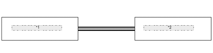
| *1 | Blind Spot Monitor Sensor LH |
| *2 | Blind Spot Monitor Sensor RH |
Figure 12. Local Bus (Models with 1GD-FTV with Urea SCR)
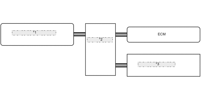
| *1 | Urea Pump Control Computer |
| *2 | CAN Junction Connector |
| *3 | Nitrogen Oxides Sensor |
Figure 13. Local Bus (Models with Automatic Headlight Beam Level Control System)
| *1 | No. 1 Headlight ECU Sub-assembly LH |
| *2 | No. 1 Headlight ECU Sub-assembly RH |
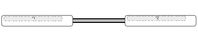
Figure 14. Local Bus (Models with Navigation System or Display Audio System)
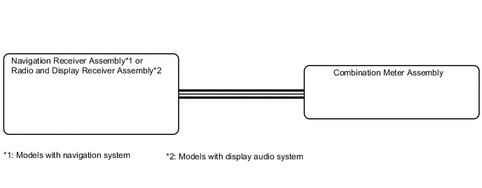
Figure 15. Local Bus (Models with Multi-terrain System)
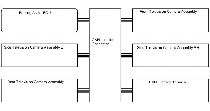
Figure 16. Local Bus (Models with Toyota Safety Sense)
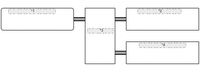
| *1 | Driving Support ECU Assembly |
| *2 | Forward Recognition Camera |
| *3 | CAN Junction Connector |
| *4 | Millimeter Wave Radar Sensor |