MULTI-TERRAIN MONITOR SYSTEM
-
FUNCTION OF MAIN COMPONENTS
Component Function Front Television Camera Assembly Outputs a video signal of the area in front of the vehicle to the parking assist ECU. Side Television Camera Assembly Outputs a video signal of the area to the side of the vehicle to the parking assist ECU. Rear Television Camera Assembly Outputs a video signal of the area to the rear of the vehicle to the parking assist ECU. Main Switch Assembly (Multi-terrain Monitor Main Switch) Switches the screen displays. Back-up Light Switch Assembly*1 Detects the shift lever position R and sends the resulting signal to the parking assist ECU. Park/Neutral Position Switch Assembly*2 Transmits the shift position signal to the ECM. Steering Angle Sensor Detects the direction and angle of the steering wheel and sends the resulting signals to the parking assist ECU. Parking Assist ECU
-
Combines video signals from the front, side and rear television camera assemblies to create a seamless overhead image.
-
Calculates each guideline based on each vehicle information signals, combines the lines with the panoramic view display and images from each television camera assembly, and outputs a video signal to the navigation receiver assembly*3 or radio and display receiver assembly*4.
-
Turns each television camera assembly on and off according to the input shift position signal and main switch assembly (multi-terrain monitor main switch).
Navigation Receiver Assembly*3
-
Displays the video signal from the parking assist ECU on the multi display.
-
Outputs the screen status to the parking assist ECU, such as when the screen display mode switches and the automatic display mode turns on and off.
Radio and Display Receiver Assembly*4
-
Displays the video signal from the parking assist ECU on the multi display.
-
Outputs the screen status to the parking assist ECU, such as when the screen display mode switches and the automatic display mode turns on and off.
Clearance Warning ECU Assembly Outputs obstacle detection information to the parking assist ECU. Skid Control ECU Transmits vehicle speed information and slip information signals to the parking assist ECU. ECM*2 Transmits shift position signals to the parking assist ECU. 4WD Control ECU Transmits transfer position signals to the parking assist ECU. Center Airbag Sensor Assembly
-
Transmits the vehicle's longitudinal and lateral acceleration signals to the parking assist ECU.
-
Transmits the vehicle's yaw rate signal to the parking assist ECU.
Main Body ECU (Driver Side Junction Block Assembly) Sends door courtesy switch information and mirror contracted state information signals to the parking assist ECU. Central Gateway ECU (Network Gateway ECU) Relays the signal between the CAN communication. *1: Models with manual transmission
*2: Models with automatic transmission
*3: Models with navigation system
*4: Models with display audio system
-
-
OPERATION CONDITION
-
The multi-terrain monitor system (manual display mode) will display under the following conditions:
Models with Automatic Transmission
-
Ignition switch is on (IG).
-
Shift position is P, N, D or S.
-
Vehicle speed is 20 km/h (12 mph) or less.
-
Main switch assembly (multi-terrain monitor main switch) is pushed.
Models with Manual Transmission
-
Ignition switch is on (IG).
-
Shift lever position is other than reverse.
-
Vehicle speed is 20 km/h (12 mph) or less.
-
Main switch assembly (multi-terrain monitor main switch) is pushed.
-
-
The multi-terrain monitor system (auto display mode) will display under the following conditions:
Models with Automatic Transmission
-
Ignition switch is on (IG).
-
Auto display mode is on.
-
When shift position selected to N, D or S.
-
When the vehicle speed becomes 10 km/h or less.*
*: When the shift position is other than R.
Models with Manual Transmission
-
Ignition switch is on (IG).
-
Auto display mode is on.
-
When the vehicle speed becomes 1.5 km/h (0.9 mph) or more.*
-
When the vehicle speed becomes 10 km/h or less.*
*: When the shift lever position is other than reverse.
-
-
-
FUNCTION
-
When the transfer is in L4 mode, the off-road screen is displayed. When in H4 mode, the on-road screen is displayed.
-
Off-Road Screens (Transfer Position L4)
Figure 1. Front View and Dual Side View Mode

Figure 2. Under Vehicle Terrain View and Dual Side View Mode

Figure 3. Rear View and Dual Side View Mode

Figure 4. Wide Rear View Mode (Models with Under Floor Mounted Spare Tire)

Figure 5. Rear View Mode (Models with Back Door Mounted Spare Tire)

-
On-road Screens (Transfer Position H4)
Figure 6. Panoramic View and Wide Front View Mode

Figure 7. Dual Side View Mode

Figure 8. Panoramic View and Rear View Mode

Figure 9. Wide Rear View Mode (Models with Under Floor Mounted Spare Tire)

Figure 10. Rear View Mode (Models with Back Door Mounted Spare Tire)

Figure 11. Side View and Wide Front View Mode (When the Outside Rear View Mirror Retracted)

Figure 12. Side View and Wide Rear View Mode (When the Outside Rear View Mirror Retracted)

Figure 13. Dual Side View Mode (When the Outside Rear View Mirror Retracted)

-
-
Multi-terrain Monitor System Display Range
-
Panoramic View
-
The display range of the panoramic view image is as follows. However, the range differs according to the vehicle and road surface conditions.
Note
The panoramic view image display range is limited and objects in the blind spot close to the vehicle or objects taller than the road surface may not be displayed. Also, the clearness at the 4 corners may be reduced. Take care when driving.
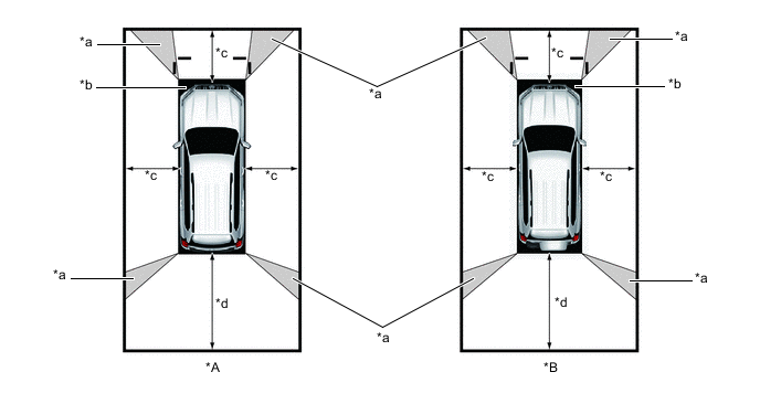
*a Image Combination Processing Area *b Blind Spot *c Approximately 2.0 m (6.6 ft.) *d Approximately 3.0 m (9.8 ft.)
-
-
Wide Front View
-
The wide front view image is an image of the following front television camera assembly imaging range. However, the range differs according to the vehicle and road surface conditions.
Note
Since the driver's sense of the distance in front of the vehicle differs from actual conditions, masking (mask area) is used.
Tech Tips
The image display range is limited. Also, since objects near either end of the bumper and objects positioned directly under and near the bumper may not be displayed, take care when driving.
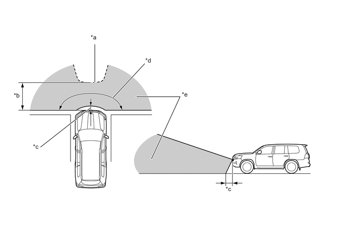
*a Mask Area *b Approximately 5.0 m (16.4 ft.) *c Approximately 0.4 m (1.3 ft.) *d Approximately 180° *e Front Television Camera Assembly Imaging Range - -
-
-
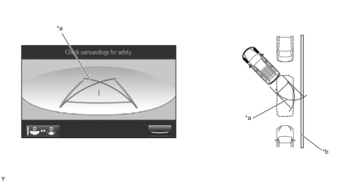
Rear View / Wide Rear View
-
The rear view/wide rear view image is an image of the following rear television camera assembly imaging range. However, the range differs according to the vehicle and road surface conditions.
Note
The image display range is limited. Also, since objects near either end of the bumper and objects positioned directly under and near the bumper may not be displayed, take care when driving.
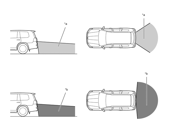
*1 Rear Television Camera Assembly Imaging Range (Rear View) *2 Rear Television Camera Assembly Imaging Range (Wide Rear View)
-
-
Dual Side View
-
The dual side view image is an image of the following side television camera assembly imaging range. However, the range differs according to the vehicle and road surface conditions.
Note
The image display range is limited, take care when driving.
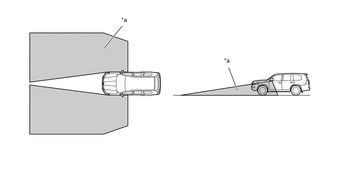
*a Side Television Camera Assembly Imaging Range - -
-
-
Side View
-
The side view image is an image of the following side television camera assembly imaging range. However, the range differs according to the vehicle and road surface conditions.
Note
The image display range is limited, take care when driving
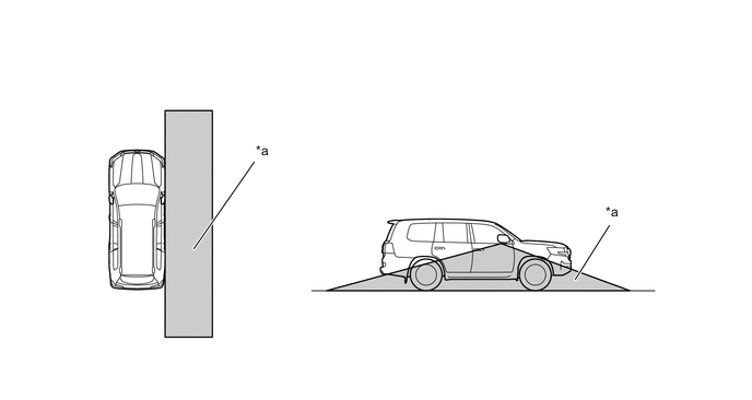
*a Side Television Camera Assembly Imaging Range - -
-
-
under Vehicle Terrain View
-
In the under vehicle terrain view mode, a view captured by the front camera when the vehicle was approximately 3 m behind its current position is displayed. On top of this image, lines indicating the current vehicle and tire positions are shown.
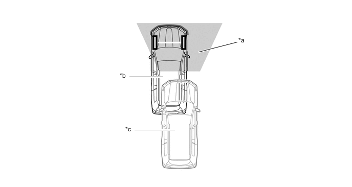
*a Current Vehicle Position *b Vehicle Position when Image Captured *c Image Captured Approximately 3 m (9.8 ft.) behind Current Vehicle Position - -
-
-
-
Display Transition
-
The manual display mode of the multi-terrain monitor system undergoes the following screen transitions:
Figure 14. Screen Transition (Transfer Position L4)
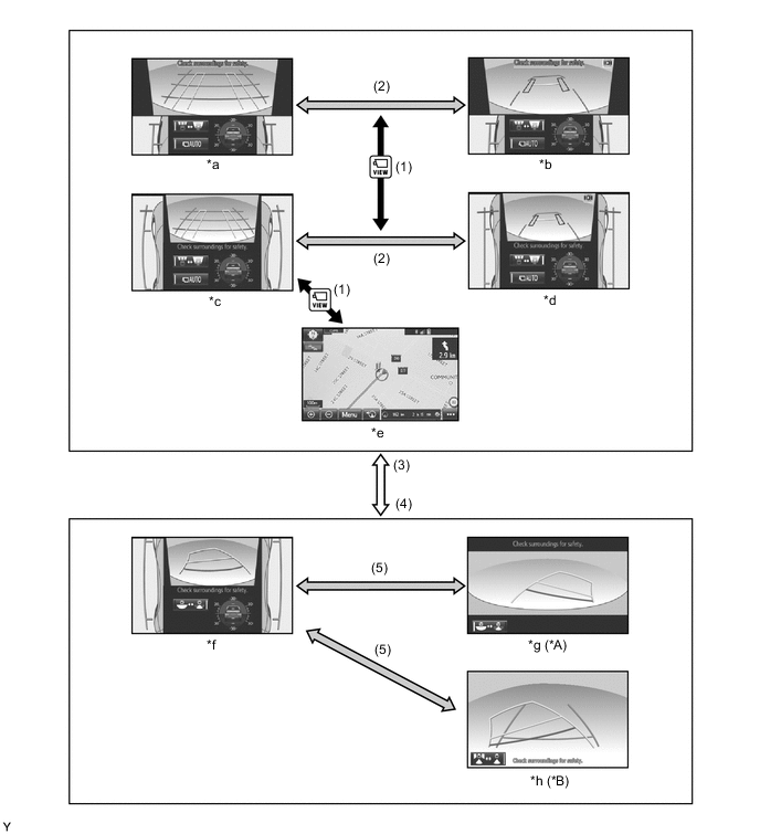
*A Models with Under Floor Mounted Spare Tire *B Models with Back Door Mounted Spare Tire *a Front View and Dual Side View Mode (Front Magnified) *b Under Vehicle Terrain View and Dual Side View Mode (Front Magnified) *c Front View and Dual Side View Mode *d Under Vehicle Terrain View and Dual Side View Mode *e Navigation Display etc. *f Rear View and Dual Side View Mode *g Wide Rear View Mode *h Rear View Mode Item Transition Condition (1) The main switch assembly (multi-terrain monitor main switch) is pressed. (2) The screen selection button is touched. (3) The shift position is P, N, D or S.*1
The Shift lever position is other than reverse.*2
(4) The shift position is R.*1
The shift lever position is reverse.*2
(5) The screen selection button is touched. *1: Models with automatic transmission
*2: Models with manual transmission
Figure 15. Screen Transition (Transfer Position H4)
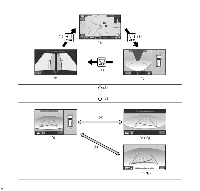
*A Models with Under Floor Mounted Spare Tire *B Models with Back Door Mounted Spare Tire *a Navigation Display etc. *b Dual Side View Mode *c Panoramic View and Wide Front View Mode *d Panoramic View and Rear View Mode *e Wide Rear View Mode *f Rear View Mode Item Transition Condition (1) The main switch assembly (multi-terrain monitor main switch) is pressed. (2) The shift position is P, N, D or S.*1
The Shift lever position is other than reverse.*2
(3) The shift position is R.*1
The shift lever position is reverse.*2
(4) The screen selection button is touched. *1: Models with automatic transmission
*2: Models with manual transmission
-
-
TOYOTA Parking Assist-sensor System Cooperative Display
-
When the TOYOTA parking assist-sensor system detects an obstacle, the obstacle detection direction and distance are displayed superimposed on the screen.
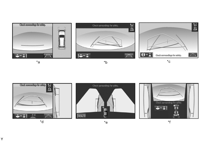
*a Panoramic View and Rear View Mode *b Wide Rear View Mode (Transfer Position H4) *c Rear View Mode (Transfer Position H4) *d Side View and Rear View Mode *e Dual Side View Mode *f Rear View and Dual Side View Mode
-
-
-
OFF-ROAD SCREEN
-
Front View and Dual Side View Mode
-
The front view and dual side view mode displays the front and both sides of the vehicle.
-
A tilt gauge that indicates the vehicle tilt has been added to the screen. Also, when a tire is spinning freely or when the TOYOTA parking assist-sensor system detects an obstacle, etc., the tilt gauge is interrupted by another screen.
-
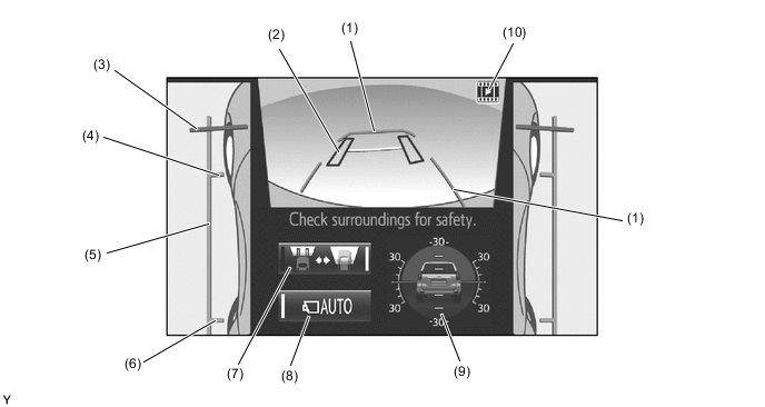
In the front view and dual side view mode, the screen displays as shown in the illustration below:
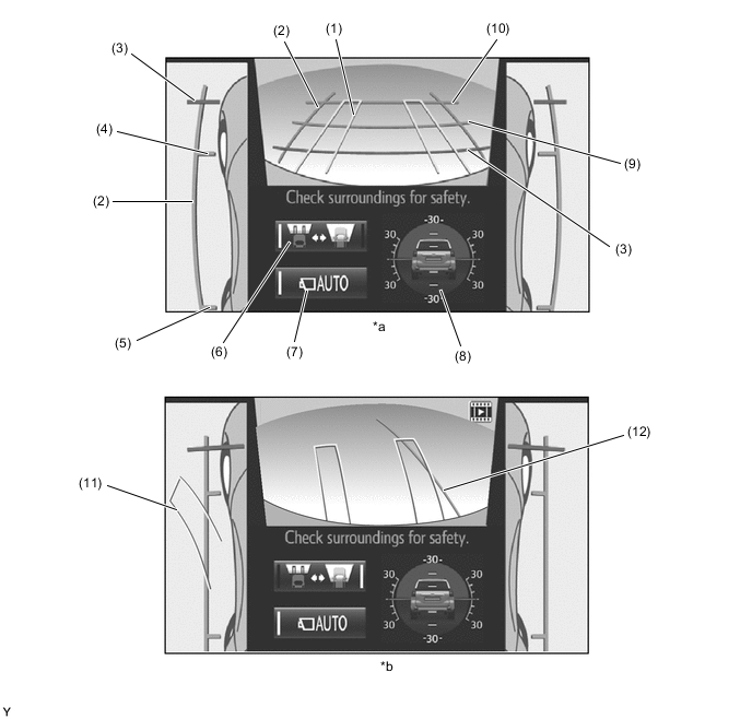
*a Normal Condition *b When Steering Wheel is Turned by 90° or more Item Description (1) Front Wheel Course Lines (Yellow) Displays the projected course of the front tires. (2) Vehicle Width Parallel Line (Blue) Displays a vehicle width guide line including the outer rear view mirror assemblies. (3) Distance Guide Line (Red) Displays approximately 0.5 m (1.6 ft.) from the front end of the vehicle. (4) Front Wheel Contact Line (Blue) Displays the front wheel positions. (5) Rear Wheel Contact Line (Blue) Displays the rear wheel positions. (6) Screen Selection Button Switches between the front view and under vehicle terrain view. (7) Automatic Display Mode Selection Button
-
Switches the automatic display mode on/off.
-
When automatic display mode is on, the operation indicator turns on.
(8) Tilt Gauge/Interruption Screen*
-
Displays the vehicle tilt.
-
When a tire is spinning freely or when the TOYOTA parking assist-sensor system detects an obstacle, etc., an interruption screen is displayed.
(9) Distance Guide Line (Blue) Displays approximately 1.0 m (3.3 ft.) from the front end of the vehicle. (10) Distance Guide Line (Blue) Displays approximately 2.0 m (6.7 ft.) from the front end of the vehicle. (11) Rear Wheel Course Lines (Yellow) Displays the projected course of the rear wheels. (12) Forward Guide Lines (Blue) Displays the course when the vehicle moves forward with the smallest turning radius. *: When a tire is spinning freely or when the TOYOTA parking assist-sensor system detects an obstacle, etc., the tilt gauge is interrupted by another screen.
-
-
While the front view and dual side view mode is displayed, the front view can be enlarged by pressing the main switch assembly (multi-terrain monitor main switch). The enlarged display is shown below.
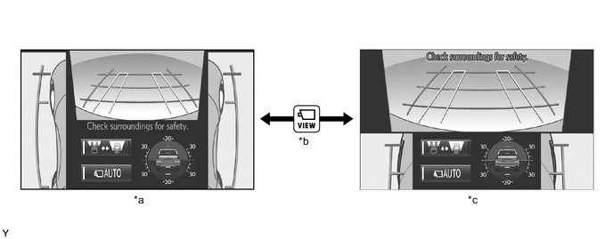
*a Normal Screen *b Pressing the Main Switch Assembly (Multi-terrain Monitor Main Switch) *c Zoom Screen - - -
The front view displays a rotating screen that shows the screen according to the tilt of the vehicle.
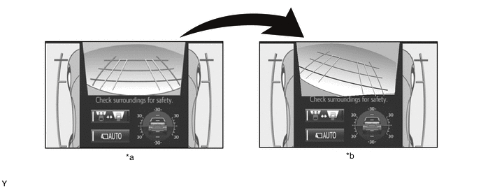
*a Normal Screen *b Rotating Screen
-
-
Under Vehicle Terrain View and Dual Side View Mode
-
The under vehicle terrain view and dual side view mode displays the vehicle underfloor (captured image of approximately 3 m (9.8 ft.) behind the current vehicle position) and both sides of the vehicle.
-
A tilt gauge that indicates the vehicle tilt has been added to the screen. Also, when a tire is spinning freely or when the TOYOTA parking assist-sensor system detects an obstacle, etc., the tilt gauge is interrupted by another screen.
-
In the under vehicle terrain view and dual side view mode, the screen displays as shown in the illustration below:
Item Description (1) Vehicle Shape Guide Lines (Blue) Displays the current approximate position of the vehicle. (2) Tire Position Guide Lines (Black) Displays the current approximate positions of the front wheels. (3) Distance Guide Line (Red) Displays approximately 0.5 m (1.6 ft.) from the front end of the vehicle. (4) Front Wheel Contact Line (Blue) Displays the front wheel positions. (5) Vehicle Width Parallel Line (Blue) Displays a vehicle width guide line including the outer rear view mirror assemblies. (6) Rear Wheel Contact Line (Blue) Displays the rear wheel positions. (7) Screen Selection Button Switches between the front view and under vehicle terrain view. (8) Automatic Display Mode Selection Button
-
Switches the automatic display mode on/off.
-
When automatic display mode is on, the operation indicator turns on.
(9) Tilt Gauge/Interruption Screen*
-
Displays the vehicle tilt.
-
When a tire is spinning freely or when the TOYOTA parking assist-sensor system detects an obstacle, etc., an interruption screen is displayed.
(10) Under Vehicle Terrain View Display Icon An icon indicating that the currently displayed screen is an image captured approximately 3 m (9.8 ft.) behind the current vehicle position. *: When a tire is spinning freely or when the TOYOTA parking assist-sensor system detects an obstacle, etc., the tilt gauge is interrupted by another screen.
-
-
-
Rear View and Dual Side View Mode
-
The rear view and dual side view mode displays the rear and both sides of the vehicle.
-
A tilt gauge that indicates the vehicle tilt has been added to the screen. Also, when a tire is spinning freely or when the TOYOTA parking assist-sensor system detects an obstacle, another vehicle, etc., the tilt gauge is interrupted by another screen.
-
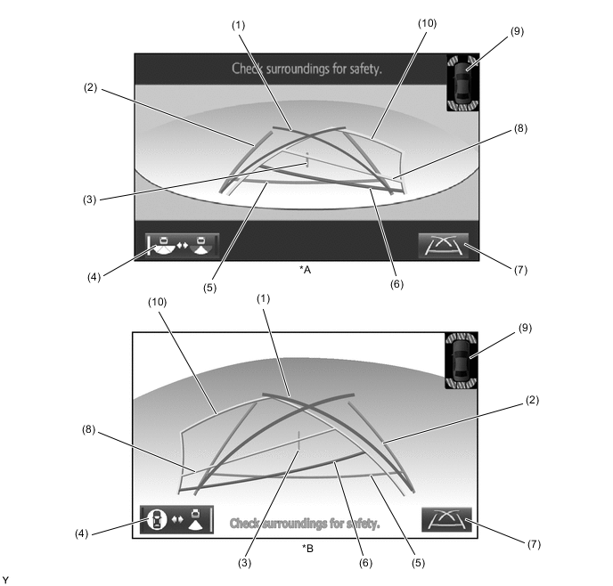
The rear view and dual side view mode, the screen displays as shown in the illustration below:
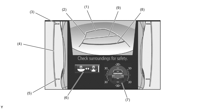
Item Description (1) Distance Guide Line (Yellow) Displays approximately 2.5 m (8.2 ft.) from the front end of the vehicle. (2) Rear Estimated Course Line (Yellow) Moves in sync with the steering wheel to indicate the estimated reverse course of the vehicle. (3) Front Wheel Contact Line (Blue) Displays the front wheel positions. (4) Vehicle Width Parallel Line (Blue) Displays a vehicle width guide line including the outer rear view mirror assemblies. (5) Rear Wheel Contact Line (Blue) Displays the rear wheel positions. (6) Camera Angle Mode Switch Button Switches between the wide rear view mode*1/rear view mode*2 and the rear view and dual side view mode. (7) Tilt Gauge/Interruption Screen*3
-
Displays the vehicle tilt.
-
When a tire is spinning freely or when the TOYOTA parking assist-sensor system detects an obstacle, another vehicle, etc., the tilt gauge is interrupted by another screen.
(8) Distance Guide Line (Red) Displays approximately 0.5 m (1.6 ft.) from the front end of the vehicle. (9) Distance Guide Line (Yellow) Displays approximately 1.0 m (3.3 ft.) from the front end of the vehicle. *1: Models with under floor mounted spare tire
*2: Models with back door mounted spare tire
*3: When a tire is spinning freely or when the TOYOTA parking assist-sensor system detects an obstacle, etc., the tilt gauge is interrupted by another screen.
-
-
-
Wide Rear View Mode/Rear View Mode
-
On models with under floor mounted spare tire, the wide rear view mode displays the rear of the vehicle.
-
On models with back door mounted spare tire, the rear view mode displays the rear of the vehicle.
-
While the rear view and dual side view mode is displayed, the wide rear view mode and rear view mode are displayed by pressing the camera angle mode switch button.
-
In the wide rear view mode and rear view mode, the screen displays as shown in the illustration below:
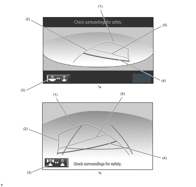
*1 Wide Rear View Mode *2 Rear View Mode Item Description (1) Distance Guide Line (Yellow) Displays approximately 2.5 m (8.2 ft.) from the front end of the vehicle. (2) Rear Estimated Course Line (Yellow) Moves in sync with the steering wheel to indicate the estimated reverse course of the vehicle. (3) Camera Angle Mode Switch Button Rear Estimated Course Line (Yellow) (4) Distance Guide Line (Red) Displays approximately 0.5 m (1.6 ft.) from the front end of the vehicle. (5) Distance Guide Line (Yellow) Displays approximately 1.0 m (3.3 ft.) from the front end of the vehicle.
-
-
Tilt Gauge/Interruption Screen
-
A screen that displays the vehicle tilt when the front view and dual side view mode, under vehicle terrain view and dual side view mode or rear view and dual side view mode is displayed has been added.
-
The tilt gauge indicates the tilt angle in the longitudinal and lateral directions within 0 ° to 30 ° using the vehicle icon and graduations.
-
When a tire is spinning freely, the tilt gauge is interrupted by another screen and the freely spinning tire is displayed in yellow.
-
When the TOYOTA parking assist-sensor system detects an obstacle, another vehicle, etc., the tilt gauge is interrupted by another screen.
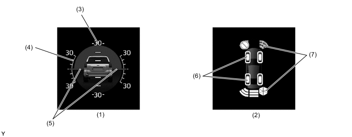
Item Description (1) Tilt Gauge Displays the vehicle state. (2) Interruption Icon* When a tire is spinning freely or when the TOYOTA parking assist-sensor system detects an obstacle, another vehicle, etc., the tilt gauge is interrupted by another screen. (3) Longitudinal Tilt Angle Graduations Displays the tilt angle in the longitudinal direction. (4) Lateral Tilt Angle Graduations Displays the tilt angle in the lateral direction. (5) Pointer (Green) Displays the current tilt angle. (6) Slip Display Shows the freely spinning tires in yellow. (7) Intuitive Parking Assist Display Indicates when the TOYOTA parking assist-sensor system detects an obstacle. *: When a tire is spinning freely or when the TOYOTA parking assist-sensor system detects an obstacle, etc., the tilt gauge is interrupted by another screen.
Note
-
The tilt angle is shown by the movement of the pointer and the tilt of the vehicle icon.
-
The color of the angle graduations changes depending on the current tilt angle.
-
After the ignition switch is turned on (IG), the tilt angle is not indicated until the tilt angle information is verified.
-
The displayed angle may differ from that calculated by other measuring devices.
-
The scale ranges between -35° to +35°, indicating the tilt angle by 5° from the center of the vehicle icon.
-
-
-
-
ON-ROAD SCREEN
-
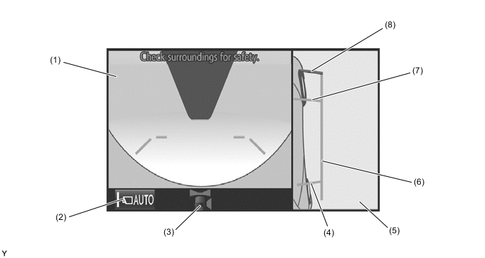
Panoramic View and Wide Front View Mode
-
The panoramic view and wide front view mode displays the vehicle front and an overhead image of the vehicle.
-
In the panoramic view and wide front view mode, the screen displays as shown in the illustration below:
Item Description (1) Wide Front View An image captured by the front television camera assembly of the area in front of the vehicle. (2) Masking Since the driver's sense of the distance in front of the vehicle differs from actual conditions, masking is used. (3) Front Distance Guide Line (Blue) These lines are distance guide lines showing the distance forward from the edge of the front bumper. (Approximately 1.0 m (3.3 ft.)) (4) Automatic Display Mode Selection Button Can be used to turn the automatic display mode on and off. When the automatic display mode is on, an indicator inside the button illuminates. (5) Camera Direction Display Vehicle Icon Indicates that the "wide front view" is displayed on the left side of the screen. (6) Display Mode Switch Button Pressing this button changes the display mode. (7) Panoramic View Vehicle Icon*1 Displays the vehicle position in the panoramic view. (8) Forward Estimated Course Line*2 (When more than 90 °)
-
Displays the estimated course calculated from the steering angle.
-
Displays the estimated course ahead of the front of the vehicle on the outside of the steering direction, and the estimated course ahead of the rear of the vehicle on the inside of the steering direction.
(9) TOYOTA Parking Assist-sensor System Cooperative Display When the TOYOTA parking assist-sensor system detects an obstacle, the obstacle detection direction and distance are displayed superimposed on the screen. (10) Panoramic View Displays an overhead image created by combining images from the front, rear, left and right side television camera assemblies. *1: The color of the panoramic view vehicle icon can be changed. For details refer to the Repair Manual.
*2: Displayed when the guide line display is set to "Estimated Course Line Display Mode" and the steering angle is not positioned straight ahead.
-
-
Estimated Course Line Display Mode
-
The forward estimated course lines assist with driving operations performed to avoid obstacles by guiding the steering angle according to the estimated course on the outside and inside of the steering direction to prevent overlapping of each guide line with obstacles, etc.
*a Forward Estimated Course Line - -
-
-
Distance Guide Line Display Mode
-
Forward perpendicular parking operations are assisted by driving forward while steering so that the front distance guide lines and front vehicle width extension lines do not overlap the curb and actual white lines, etc.
-
-
-
Dual Side View
-
The dual side views mode shows the conditions in the sides of the vehicle.
-
The dual side views mode, the screen displays as shown in the illustration below:
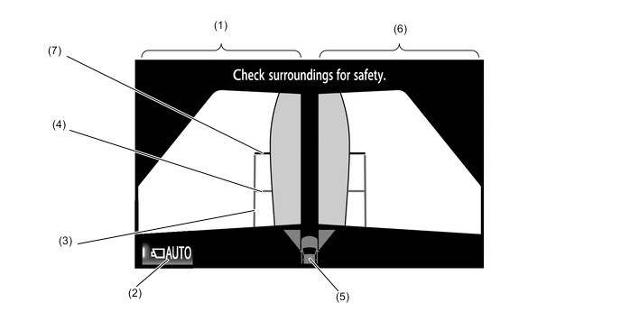
Item Description (1) Side View (Front Left Side) Screen An image captured by the side television camera assembly LH of the area to the front left side of the vehicle. (2) Automatic Display Mode Selection Button Can be used to turn the automatic display mode on and off. When the automatic display mode is on, an indicator inside the switch illuminates. (3) Vehicle Width Parallel Line (Blue) A vehicle width guide line including the outer rear view mirror assembly. (4) Front Tire Contact Line (Blue) A guide line showing the front tire contact position. (5) Camera Direction Display Vehicle Icon
-
Indicates that the side views screen is displayed.
-
When the TOYOTA parking assist-sensor system detects an obstacle, the icon changes to the TOYOTA parking assist-sensor system icon.
(6) Side View (Front Right Side) Screen An image captured by the side television camera assembly RH of the area to the front right side of the vehicle. (7) Front Distance Guide Line (Red) These lines are distance guide lines showing the distance forward from the edge of the front bumper. (Approx. 0.5 m (1.6 ft.)) -
-
When the outside rear view mirrors are retracted, the following screen is displayed.
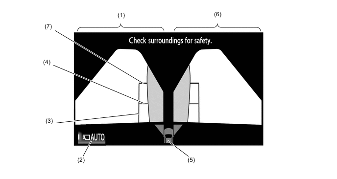
Item Description (1) Side View (Front Left Side) Screen An image captured by the side television camera assembly LH of the area to the front left side of the vehicle. (2) Automatic Display Mode Selection Button Can be used to turn the automatic display mode on and off. When the automatic display mode is on, an indicator inside the switch illuminates. (3) Vehicle Width Parallel Line (Blue) A vehicle width guide line including the outer rear view mirror assembly. (4) Front Tire Contact Line (Blue) A guide line showing the front tire contact position. (5) Camera Direction Display Vehicle Icon
-
Indicates that the side views screen is displayed.
-
When the TOYOTA parking assist-sensor system detects an obstacle, the icon changes to the TOYOTA parking assist-sensor system icon.
(6) Side View (Front Right Side) Screen An image captured by the side television camera assembly RH of the area to the front right side of the vehicle. (7) Front Distance Guide Line (Red) These lines are distance guide lines showing the distance forward from the edge of the front bumper. (Approx. 0.5 m (1.6 ft.)) -
-
-
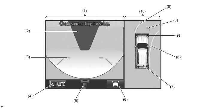
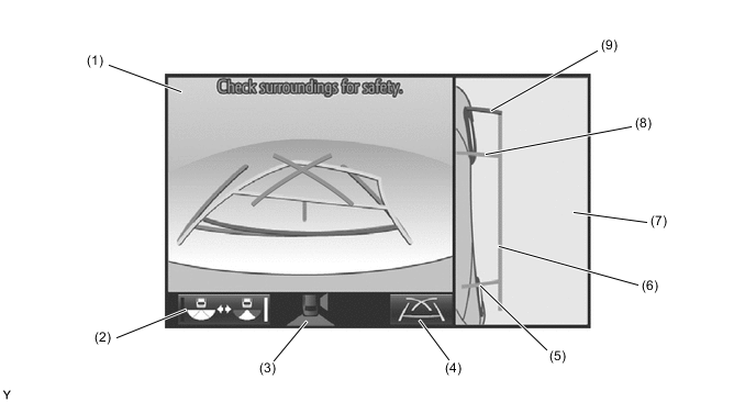
Panoramic View and Rear View Mode
-
The panoramic view and rear view mode displays the vehicle rear and an overhead image of the vehicle.
-
In the panoramic view and rear view mode, the screen displays as shown in the illustration below:
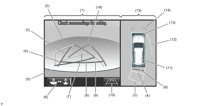
Item Description (1) Rear View An image captured by the rear television camera assembly of the area to the rear of the vehicle. (2) Rear Estimated Course Line*1 (Yellow) Moves in sync with the steering wheel to indicate the estimated reverse course of the vehicle. (3) Rear Vehicle Width Extension Line*2 (Blue) Indicates the estimated vehicle width. (4) Rear Distance Guide Line (Yellow/Red)*3 These lines are distance guide lines showing the distance from the edge of the rear bumper. (Approximately 1.0 m (3.3 ft.): yellow, approximately 0.5 m (1.6 ft.): red) (5) Edge of Rear Bumper The edge of the rear bumper is displayed on the screen. (6) Camera Angle Mode Switch Button Switches the wide rear view. (7) Vehicle Center Guide Line (Blue) Indicates the estimated position on the ground of the center of the vehicle. (8) Rear Distance Guide Line (Yellow/Red)*3 These lines are distance guide lines showing the distance from the edge of the rear bumper. (Approximately 1.0 m (3.3 ft.): yellow, approximately 0.5 m (1.6 ft.): red) (9) Rear Distance Guide Line (Blue)*4 These lines are distance guide lines showing the distance from the edge of the rear bumper. (Approximately 0.5 m (1.6 ft.)) (10) Display Mode Switch Button Pressing this button changes the display mode. (11) Panoramic View Vehicle Icon*5 Displays the vehicle position in the panoramic view. (12) Side Estimated Course Line*3 (Yellow)
-
Displays the estimated course calculated from the steering angle.
-
Displays the estimated course on the outside of the steering direction.
(13) TOYOTA Parking Assist-sensor System Cooperative Display When the TOYOTA parking assist-sensor system detects an obstacle, the obstacle detection direction and distance are displayed superimposed on the screen. (14) Front Distance Guide Line (Blue) These lines are distance guide lines showing the distance forward from the edge of the front bumper. (Approximately 1.0 m (3.3 ft.)) (15) Panoramic View Displays an overhead image created by combining images from the front, rear, left and right side television camera assemblies. (16) Parking Assist Guide Line*6 (Blue) Indicates the path the vehicle will follow when the driver turns the steering wheel fully. *1: Displayed when the guide line display is set to "Estimated Course Line Display Mode".
*2: Not displayed when the steering angle is approximately straight ahead.
*3: Displayed when the guide line display is set to "Estimated Course Line Display Mode" and the steering angle is not positioned straight ahead.
*4: Turns red in "Parking Assist Guide Line Display Mode" and "Distance Guide Line Display Mode".
*5: The color of the panoramic view vehicle icon can be changed. For details, refer to the Repair Manual.
*6: The side estimated course line or rear estimated course line and the parking assist guide line cannot be displayed simultaneously.
-
-
Estimated Course Line Display Mode (Perpendicular Parking)
-
The rear vehicle width extension lines can be used to determine whether the vehicle is parked straight in the parking space by confirming whether the parking space lines and rear vehicle width extension lines are crossed or parallel.
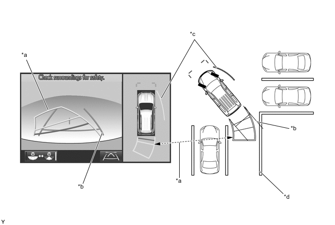
*a Rear Estimated Course Line *b Rear Vehicle Width Extension Line *c Side Estimated Course Line *d Parking Space Line
-
-
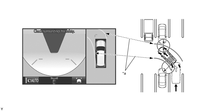
Estimated Course Line Display Mode (Parallel Parking)
-
The rear vehicle width extension lines can be used to determine whether the vehicle is parked straight in the desired parking position by confirming the status of the shoulder and parking space lines, etc., and rear vehicle width extension lines.
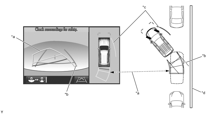
*a Rear Estimated Course Line *b Rear Vehicle Width Extension Line *c Side Estimated Course Line *d Shoulder and Parking Space Lines, etc.
-
-
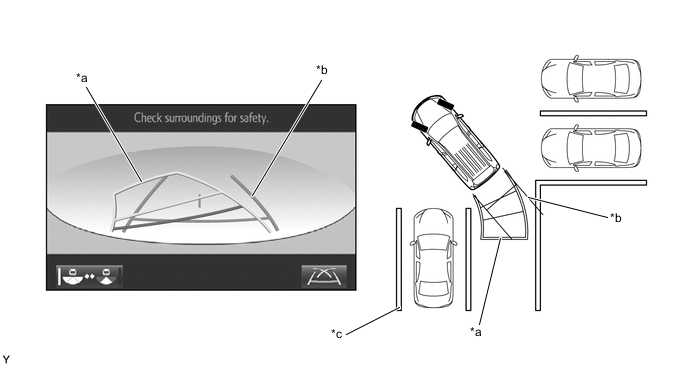
Parking Assist Guide Line Display Mode (Perpendicular Parking)
-
The parking assist guide line can be used to determine whether the vehicle is parked straight in the parking space by confirming whether the parking space lines and parking assist guide line are crossed or parallel.
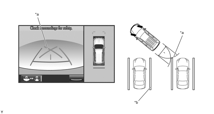
*a Parking Assist Guide Line *b Parking Space Line
-
-
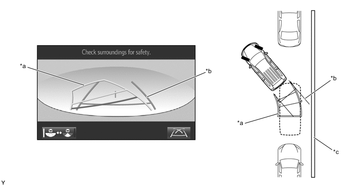
Parking Assist Guide Line Display Mode (Parallel Parking)
-
The parking assist guide line can be used to determine whether the vehicle is parked straight in the desired parking position by confirming the status of the shoulder and parking space lines, etc., and parking assist guide line.
-
-
-
Wide Rear View Mode/Rear View Mode
-
The wide rear view mode/rear view mode displays the rear of the vehicle.
-
The wide rear view mode/rear view mode is displayed when the camera angle mode switch button is pressed during display of the panoramic view and rear view mode.
-
In the wide rear view mode/rear view mode, the screen displays as shown in the illustration below:
*A Models with Under Floor Mounted Spare Tire *B Models with Back Door Mounted Spare Tire Item Description (1) Parking Assist Guide Line*1 (Blue) Indicates the path the vehicle will follow when the driver turns the steering wheel fully. (2) Rear Vehicle Width Extension Line*2 (Blue) Indicates the estimated vehicle width. (3) Vehicle Center Guide Line (Blue) Indicates the estimated position on the ground of the center of the vehicle. (4) Camera Angle Mode Switch Button Switches the rear view. (5) Rear Distance Guide Line (Blue)*3 These lines are distance guide lines showing the distance from the edge of the rear bumper. (Approximately 0.5 m (1.6 ft.)) (6) Rear Distance Guide Line (Yellow/Red)*4 These lines are distance guide lines showing the distance from the edge of the rear bumper. (Approximately 1.0 m (3.3 ft.): yellow, approximately 0.5 m (1.6 ft.): red) (7) Display Mode Switch Button Pressing this button changes the display mode. (8) Rear Distance Guide Line (Yellow/Red)*4 These lines are distance guide lines showing the distance from the edge of the rear bumper. (Approximately 1.0 m (3.3 ft.): yellow, approximately 0.5 m (1.6 ft.): red) (9) Interruption Icon Displayed when the TOYOTA parking assist-sensor system detects an obstacle, another vehicle, etc. (10) Rear Estimated Course Line*5 (Yellow) Moves in sync with the steering wheel to indicate the estimated reverse course of the vehicle. *1: The rear estimated course line and the parking assist guide line cannot be displayed simultaneously.
*2: Turns red in "Parking Assist Guide Line Display Mode" and "Distance Guide Line Display Mode".
*3: Not displayed when the steering angle is approximately straight ahead.
*4: Displayed when the guide line display is set to "Estimated Course Line Display Mode" and the steering angle is not positioned straight ahead.
*5: Displayed when the guide line display is set to "Estimated Course Line Display Mode".
-
Estimated Course Line Display Mode (Perpendicular Parking)
-
The rear vehicle width extension lines can be used to determine whether the vehicle is parked straight in the parking space by confirming whether the parking space lines and rear vehicle width extension lines are crossed or parallel.
*a Parking Assist Guide Line *b Rear Vehicle Width Extension Line *c Parking Space Line - -
-
-
Estimated Course Line Display Mode (Parallel Parking)
-
The rear vehicle width extension lines can be used to determine whether the vehicle is parked straight in the desired parking position by confirming the status of the shoulder and parking space lines, etc., and rear vehicle width extension lines.
*a Rear Estimated Course Line *b Rear Vehicle Width Extension Line *c Shoulder and Parking Space Lines, etc. - -
-
-
Parking Assist Guide Line Display Mode (Perpendicular Parking)
-
The parking assist guide line can be used to determine whether the vehicle is parked straight in the parking space by confirming whether the parking space lines and parking assist guide line are crossed or parallel.
*a Parking Assist Guide Line *b Parking Space Line
-
-
Parking Assist Guide Line Display Mode (Parallel Parking)
-
The parking assist guide line can be used to determine whether the vehicle is parked straight in the desired parking position by confirming the status of the shoulder and parking space lines, etc., and parking assist guide line.
*a Parking Assist Guide Line *b Shoulder and Parking Space Lines, etc.
-
-
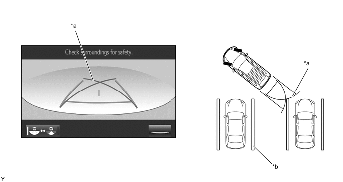
Distance Guide Line Display Mode
-
In this mode, only a distance guide line is displayed when the driver does not need other guide lines.
-
-
-
Side View and Wide Front View Mode
-
When the outside rear view mirrors are retracted, the screen switches from the wide front view and panoramic mode to the side view and wide front view mode.
-
The side view and wide front view mode displays the front passenger side and front of the vehicle.
-
In the side view and wide front view mode, the screen displays as shown in the illustration below:
Item Description (1) Wide Front View An image captured by the front television camera assembly of the area in front of the vehicle. (2) Automatic Display Mode Selection Button Can be used to turn the automatic display mode on and off. When the automatic display mode is on, an indicator inside the button illuminates. (3) Camera Direction Display Vehicle Icon Indicates that the "wide front view" is displayed on the left side of the screen. (4) Rear Tire Contact Line (Blue) A guide line showing the rear right tire contact position. (5) Side View (Right Side) An image of the area to the right of the vehicle captured by the side television camera assembly RH. (6) Vehicle Width Parallel Line (Blue) A vehicle width guide line including the outer rear view mirror assembly. (7) Front Tire Contact Line (Blue) A guide line showing the front right tire contact position. (8) Front Distance Guide Line (Red) This line is distance guide line showing the distance forward from the edge of the front bumper. (Approximately 0.5 m (1.6 ft.))
-
-
Side View and Rear View Mode
-
When the outside rear view mirrors are retracted, the screen switches from the panoramic view and rear view mode to the side view and rear view mode.
-
The side view and rear view mode displays the front passenger side and rear of the vehicle.
-
In the side view and rear view mode, the screen displays as shown in the illustration below:
Item Description (1) Rear View An image captured by the rear television camera assembly of the area to the rear of the vehicle. (2) Camera Angle Mode Switch Button Switches the rear view. (3) Camera Direction Display Vehicle Icon Indicates that the "wide front view" is displayed on the left side of the screen. (4) Display Mode Switch Button Pressing this button changes the display mode. (5) Rear Tire Contact Line (Blue) A guide line showing the rear right tire contact position. (6) Vehicle Width Parallel Line (Blue) A vehicle width guide line including the outer rear view mirror assembly. (7) Side View (Right Side) An image of the area to the right of the vehicle captured by the side television camera assembly RH. (8) Front Tire Contact Line (Blue) A guide line showing the front right tire contact position. (9) Front Distance Guide Line (Red) This line is distance guide line showing the distance forward from the edge of the front bumper. (Approximately 0.5 m (1.6 ft.))
-
-
-
CONSTRUCTION AND OPERATION
-
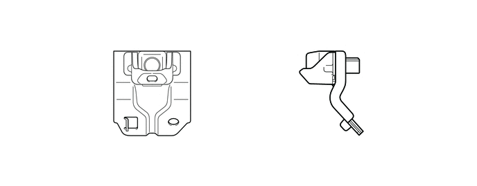
Television Camera Assembly
-
The television camera assemblies consists of a screen input component with a wide-angle lens and a video signal output component with a small type color Complementary Metal Oxide Semiconductor (CMOS) camera.
Figure 16. Front Television Camera Assembly
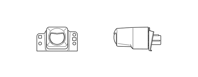
Figure 17. Side Television Camera Assembly LH
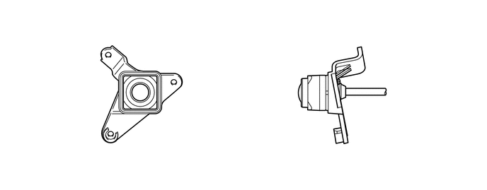
Figure 18. Side Television Camera Assembly RH
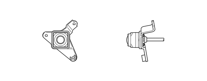
Figure 19. Rear Television Camera Assembly (Models with Under Floor Mounted Spare Tire)
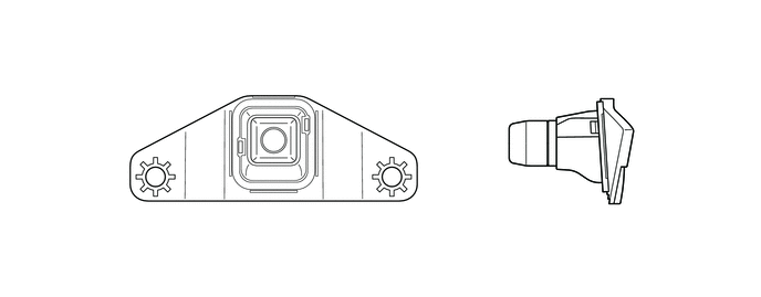
Figure 20. Rear Television Camera Assembly (Models with Back Door Mounted Spare Tire)
-
-
-
DIAGNOSIS
-
The multi-terrain monitor system is equipped with a diagnosis function which can display the service menus. The method for entering the service menu screen is the same as the method used for the multi display. For details, refer to the Repair Manual.
-