MULTI-TERRAIN MONITOR SYSTEM
-
FUNCTION OF MAIN COMPONENTS
Component Function Navigation Receiver Assembly*1 or Radio and Display Receiver Assembly*2 Receives image signals transmitted from the parking assist ECU and displays them. Parking Assist ECU
-
Turns the multi-terrain monitor system on/off in accordance with the signals input from the ECU and switches.
-
Outputs visual signals from the front television camera, the side television camera and the rear television camera to the navigation receiver assembly*1 or radio and display receiver assembly*2.
Monitor Switch Switches between the screen of the multi-terrain monitor system. Television Camera Assemblies Output the images received by television camera assemblies installed on the radiator grille, outer rear view mirror assembly and back door*3 or back door spare tire carrier*4 to the parking assist ECU. Skid Control ECU Outputs vehicle speed signals to the parking assist ECU. ECM Transmits shift position signals to the parking assist ECU. Main Body ECU (Driver Side Junction Block Assembly) Sends information such as steering signals to the parking assist ECU. Steering Angle Sensor Detects the steering angle and transmits signals to the parking assist ECU. Clearance Warning ECU Assembly*5 Sends clearance sensor detection information to the parking assist ECU. Park/Neutral Position Switch Assembly*6 Transmits a signal telling the ECM or TCM*7 that the shift lever is in R. Back-up Light Switch Assembly*8 Transmits a signal telling the ECM that the shift lever is in R. TCM*7 Sends received shift position signals to the ECM.
-
*1: Models with navigation system
-
*2: Models with display audio system
-
*3: Models without back door spare tire carrier
-
*4: Models with back door spare tire carrier
-
*5: Models with TOYOTA parking assist-sensor system
-
*6: Models with automatic transmission
-
*7: Models with 1KD-FTV engine with automatic transmission
-
*8: Models with manual transmission
-
-
OPERATING CONDITION
-
The multi-terrain monitor system will display under the following conditions:
-
Engine switch is on (IG) or on (ACC).
-
Transfer is in L4 mode.
-
Vehicle speed is 10 km/h (6 mph) or less.
-
Multi-terrain monitor system is on.
-
-
-
FUNCTION
-
Area Displayed on Screen
-
The front, rear and side television camera assemblies can capture images within the area shown below. However, the display area may differ, depending on the conditions of the vehicle or the road.
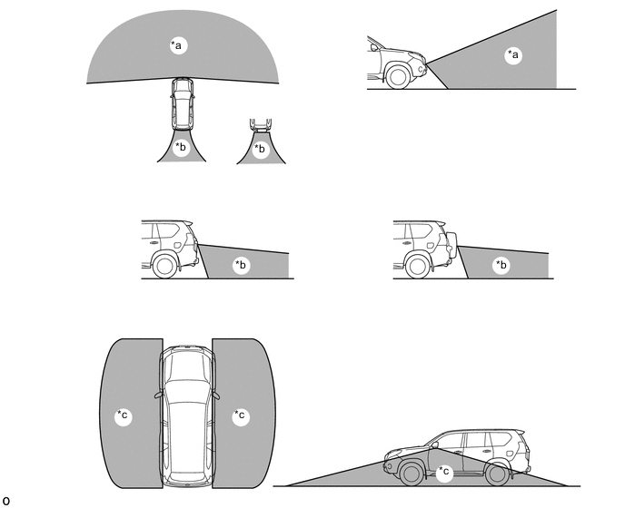
Text in Illustration *a Front Television Camera Assembly Capture Range *b Rear Television Camera Assembly Capture Range *c Side Television Camera Assembly Capture Range - -
-
-
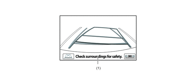
Front View Mode
-
The front view mode shows the conditions in front of the vehicle.
-
In the front view mode, the screen displays as shown in the illustration below:
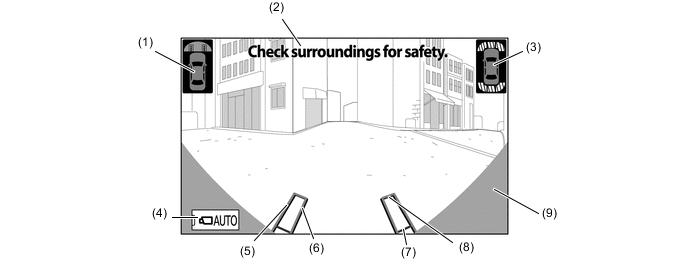
Item Description of Display (1) Vehicle Icon Shows the display range of the front view mode. (2) Warning Message Display Area Displays a warning message. (3) TOYOTA Parking Assist-sensor System Icon Shows the obstacle detection position of the TOYOTA parking assist-sensor system. (4) AUTO Mode Switch Turns the AUTO mode on and off. (5) Trajectory Line (Outside) Indicates the outer path of the wheel. (6) Trajectory Line (Inside) Indicates the inner path of the wheel. (7) Distance Guide Line (Red) Shows a point approx. 0.5 m (1.6 ft.) ahead of the front edge of the vehicle. (8) Distance Guide Line (Yellow) Shows a point approx. 1.0 m (3.3 ft.) ahead of the front edge of the vehicle. (9) Parts Which Show The Vehicle Parts which show same of the radiator grille and bumper. (Does not show the bumper corners.)
-
-
Side Front Simultaneous View Mode
-
The side front simultaneous view mode shows the conditions in side of the vehicle.
-
In the side front simultaneous view mode, the screen displays as shown in the illustration:
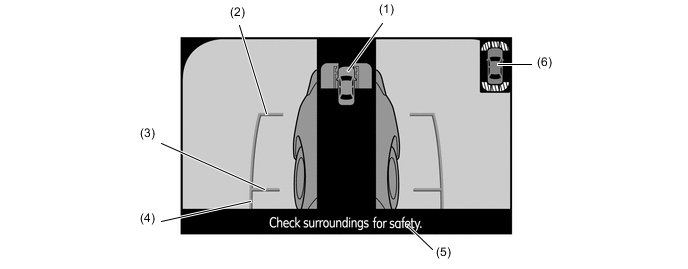
Item Description of Display (1) Vehicle Icon Shows the screen display range of the side front simultaneous view mode. (2) Vehicle Front Edge Shows the front edge of the vehicle using a guide line. (3) Front Wheel Road Contact Line Shows the position of the front wheels. (4) Vehicle Parallel Line Shows the vehicle width including the outer rear view mirrors by displaying lines that run parallel with the body line. (5) Warning Message Display Area Displays a warning message. (6) TOYOTA Parking Assist-sensor System Icon Shows the obstacle detection position of the TOYOTA parking assist-sensor system.
-
-
Side Rear Simultaneous View Mode
-
The side rear simultaneous view mode shows the conditions in side of the vehicle.
-
In the side rear simultaneous view mode, the screen displays as shown in the illustration below:
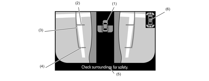
Item Description of Display (1) Vehicle Icon Shows the screen display range of the side front simultaneous view mode. (2) Rear Wheel Road Contact Line Shows the position of the rear wheels. (3) Vehicle Parallel Line Shows the vehicle width including the outer rear view mirrors by displaying lines that run parallel with the body line. (4) Vehicle Rear Edge Shows the rear edge of the vehicle using a guide line. (5) Warning Message Display Area Displays a warning message. (6) TOYOTA Parking Assist-sensor System Icon Shows the obstacle detection position of the TOYOTA parking assist-sensor system.
-
-
Rear View Mode
-
The parking assist mode shows the conditions in rear of the vehicle.
-
In the rear view mode, the screen displays as shown in the illustration below:
Item Description of Display (1) Warning Message Display Area Displays a warning message.
-
-
Warning Message
-
A warning message appears at the bottom, side or center of the screen under the conditions listed below. The warning message appears in the language that has been selected by the language selector of the navigation screen display.
Messages Appearing at Bottom or Side of Screen Warning Message Outline Check surroundings for safety This message always appears during system operation.
-
-
-
CONSTRUCTION
-
Television Camera Assembly
-
The front television camera assembly consists of a wide angle lens and a Charge Coupled Device (CCD).
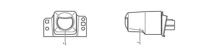
Text in Illustration *1 Front Television Camera Assembly - - -
The side and rear television camera assembly consists of a wide-angle lens and a Complementary Metal Oxide Semiconductor (CMOS).
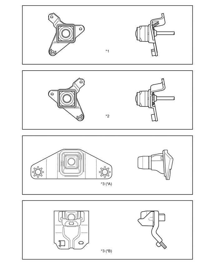
Text in Illustration *A Models without Spare Tire Back Door Carrier *B Models with Spare Tire Back Door Carrier *1 Side Television Camera Assembly LH *2 Side Television Camera Assembly RH *3 Rear Television Camera Assembly - -
-
-
-
OPERATION
-
Display Transition
-
The multi-terrain monitor display mode of the multi-terrain monitor system undergoes the following screen transitions:
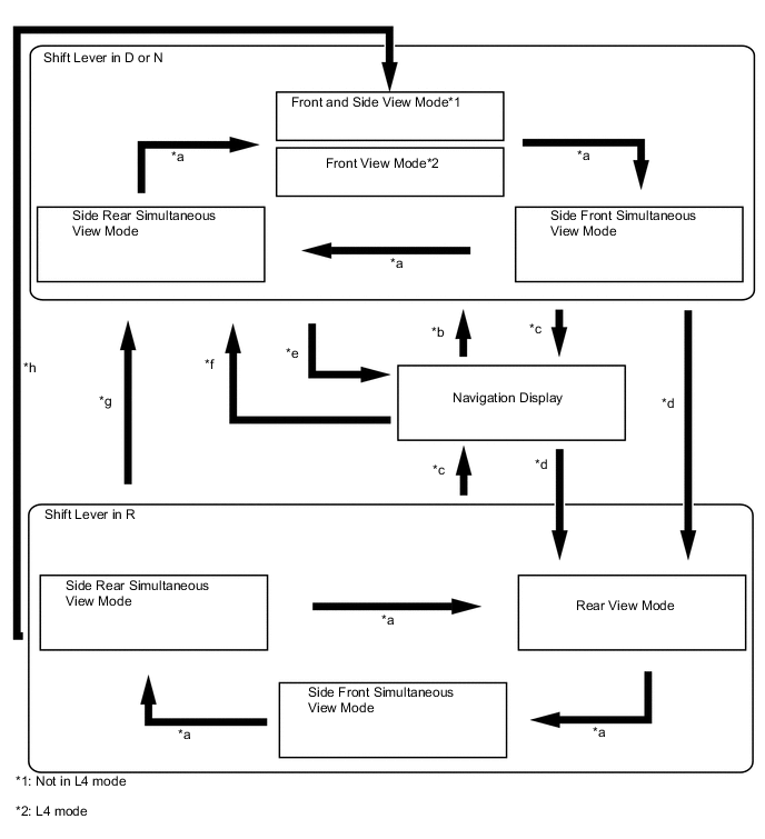
Item Transition Condition *a The monitor switch is operated. *b The monitor switch is pressed when the shift lever is in D or N. *c The map switch is pressed, or the shift lever is moved to P. *d The shift lever is in R. *e The vehicle speed has increased from 12 km/h (7.5 mph) or less to more than 12 km/h (7.5 mph). (During AUTO mode) *f The vehicle speed has dropped from more than 12 km/h (7.5 mph) or less. (During AUTO mode) *g The shift lever is in a position other than P and R. (L4 mode) *h The shift lever is in a position other than P and R. (Not in L4 mode)
-
-
-
FAIL-SAFE
-
The table below indicates the conditions of detecting malfunctions in the components of this system.
Malfunction Parts Detection Item Function Television Camera Assemblies Transmission of television camera malfunction signal Stops signal reception and displays a dark screen Parking Assist ECU Malfunction of parking assist ECU Stops system operation
-
-
DIAGNOSIS
-
The multi-terrain monitor system is equipped with a diagnosis function which can display the service menus. For details, refer to the Repair Manual.
-