STEERING COLUMN SYSTEM
-
FUNCTION OF MAIN COMPONENTS
Model with Power Tilt and Power Telescopic System Component Function Multiplex Tilt and Telescopic ECU Calculates position information and operating conditions using signals from the position sensor, the tilt and telescopic switch and the CAN network, and controls the tilt motor and telescopic motor. Steering Column Assembly Tilt Motor and Telescopic Motor Adjusts the position of the steering column assembly in accordance with the voltage output of the multiplex tilt and telescopic ECU. Tilt Position Sensor and Telescopic Position Sensor Detects the rotation signal of the tilt motor and telescopic motor and informs the multiplex tilt and telescopic ECU. Tilt and Telescopic Switch Sends a switch signal to the multiplex tilt and telescopic ECU depending on the switch operation. Main Body ECU (Driver Side Junction Block Assembly) Sends a seat memory switch signal to the position control ECU. Position Control ECU Sends the memorized position information to the multiplex tilt and telescopic ECU. Certification ECU (Smart Key ECU Assembly) Sends an engine switch signal to the multiplex tilt and telescopic ECU. -
SYSTEM CONTROL
-
The power tilt and power telescopic system has the following control functions:
Control Outline Manual Control The tilt and telescopic positions can be adjusted using the tilt and telescopic switch. Automatic Control Auto Away The steering wheel automatically tilts up and retracts all the way when the engine switch is turned from on (ACC) or on (IG) to off. Auto Return When the engine switch is turned from off to on (ACC) or on (IG), the steering wheel automatically returns to the previous position which was set before the engine switch was turned off. Memory Control The memory function can store the driver seat position and tilt and telescopic position. Up to 2 memory positions can be stored in the system memory and recalled. 2 positions can be saved for the seat memory switch.
-
-
CONSTRUCTION
-
Steering Column Assembly (Model with Power Tilt and Power Telescopic System)
-
The steering column assembly consists of a steering main shaft, tilt motor, telescopic motor and multiplex tilt and telescopic ECU.
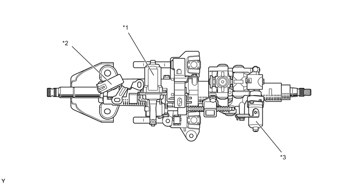
*1 Telescopic Motor *2 Multiplex Tilt and Telescopic ECU *3 Tilt Motor - -
-
-
Manual Tilt and Telescopic Mechanism
-
The manual tilt and telescopic mechanism allows adjustment of the steering wheel position in the vertical and longitudinal (extending and retracting) directions through lever operation. This provides the driver with the most comfortable driving position.
-
The manual tilt and telescopic mechanism is locked using the tilt and telescopic lever.
-
The tilt adjustment range is 40.0 mm (1.57 in.).
-
The telescopic adjustment range is 40.0 mm (1.57 in.).
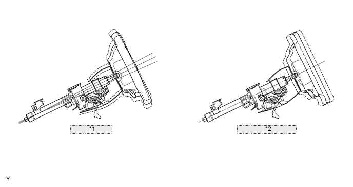
*1 Tilt Mechanism *2 Telescopic Mechanism
-
-
Power Tilt and Power Telescopic System
-
A stepless adjustment enables the tilt mechanism to be tilted 69.0 mm (2.72 in.) vertically, and the telescopic mechanism to be moved 45.0 mm (1.77 in.) longitudinally.
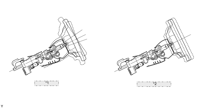
*1 Tilt Mechanism *2 Telescopic Mechanism
-
-
Energy Absorbing Mechanism
-
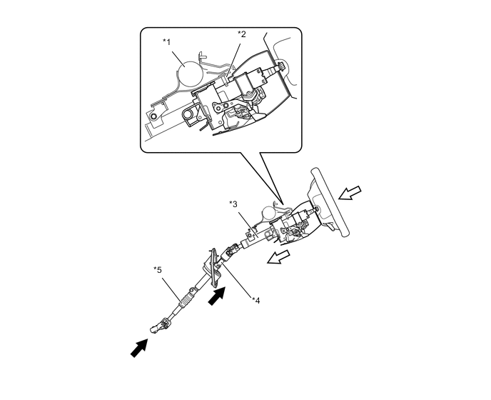
The energy absorbing mechanism mainly consists of a breakaway bracket, steering intermediate shaft assembly, steering intermediate shaft sub-assembly No. 2 and column tube. The steering column assembly is mounted on the instrument panel reinforcement via the breakaway bracket. The steering column assembly and the steering gear assembly are connected with the contractile intermediate shaft.
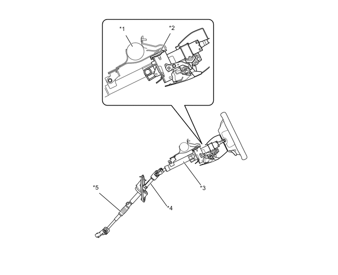
Text in Illustration (before Collision) *1 Instrument Panel Reinforcement *2 Breakaway Bracket *3 Column Tube *4 Steering Intermediate Shaft Assembly *5 Steering Intermediate Shaft Sub-assembly No. 2 - - -
When the steering gear assembly moves during a collision (primary collision), the steering intermediate shaft sub-assembly No. 2 contracts, thus helping reduce the possibility of the steering column assembly and the steering wheel protruding into the cabin.
-
When a collision impact is transmitted to the steering wheel (secondary collision), the steering wheel and the airbag help absorb the impact.
-
On models with a manual tilt and telescopic mechanism, the breakaway bracket and the instrument panel reinforcement separate, and the column tube contracts.
-
On models with a power tilt and power telescopic system, the energy absorbing plate deforms, and the column tube contracts.
Text in Illustration (after Collision) *1 Instrument Panel Reinforcement *2 Breakaway Bracket *3 Column Tube *4 Steering Intermediate Shaft Assembly *5 Steering Intermediate Shaft Sub-assembly No. 2 - - 
Primary Collision 
Secondary Collision -
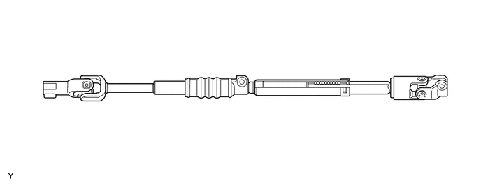
By using a permanently expandable and contractible steering intermediate shaft assembly and a steering intermediate shaft sub-assembly No. 2 that deforms and contracts during collisions, safety during collisions is ensured and a smooth steering feeling is achieved.
-
-
-
FAIL-SAFE
-
When the multiplex tilt and telescopic ECU detects a malfunction in the power tilt and power telescopic system, the ECU changes to fail-safe mode. For details, refer to the Repair Manual.
-
-
DIAGNOSIS
-
If the multiplex tilt and telescopic ECU detects a malfunction in the power tilt and power telescopic system, the ECU stores the malfunction data in memory. Then, by connecting the Global TechStream (GTS) to the DLC3 terminal, the Diagnostic Trouble Codes (DTCs) can be accessed and an active test can be performed to test the operation of the tilt motor and the telescopic motor. For details, refer to the Repair Manual.
-