KINETIC DYNAMIC SUSPENSION SYSTEM
-
FUNCTION OF MAIN COMPONENTS
Component Function Front and Rear Stabilizer Bars Restrain roll to ensure driving stability. Front and Rear Stabilizer Control Cylinders Absorb the impact from the road surface to ensure ride comfort. Stabilizer Control with Accumulator Housing Assembly Accumulator Pressure Sensor Detects the hydraulic pressure and transmits its signal to the stabilizer control ECU. Stabilizer Control Solenoid Valve Opens and closes the piping between each stabilizer control cylinder chamber and the accumulator. Accumulator Absorbs the pressure from the front stabilizer with tube cylinder assembly and rear stabilizer control cylinder. Combination Meter Assembly KDSS Indicator Light Illuminates to inform the driver when the stabilizer control ECU has detected a malfunction in the KDSS. Steering Angle Sensor Detects the steering direction and the angle of the steering wheel. Center Airbag Sensor Assembly Yaw Rate Sensor Detects the vehicle's yaw rate. Deceleration Sensor Detects the vehicle's longitudinal and lateral acceleration and deceleration. Stabilizer Control ECU Switches the stabilizer control valve based on the signals from the sensors and ECUs. Skid Control ECU Sends the vehicle speed signal to the stabilizer control ECU. -
CONSTRUCTION
-
Stabilizer Control Cylinder
-
The stabilizer control cylinder consists of the piston, upper chamber and lower chamber. There is no connection between the upper chamber and lower chamber.
-
The upper chamber of the front stabilizer control cylinder is connected to the upper chamber of the rear stabilizer control cylinder.
-
The lower chamber of the front stabilizer control cylinder is connected to the lower chamber of the rear stabilizer control cylinder.
-
A bleeder plug is provided for each chamber. To remove the stabilizer control cylinder, fluid must be drained from the bleeder plug.
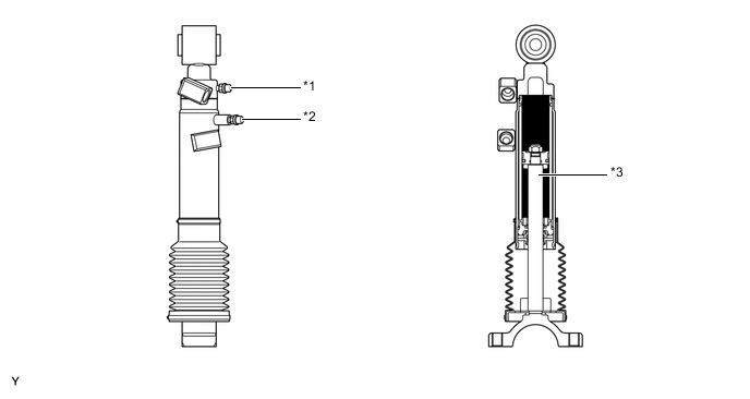
Text in Illustration (Front Stabilizer Control Cylinder) *1 Bleeder Port (for Upper Chamber) *2 Bleeder Port (for Lower Chamber) *3 Piston - - 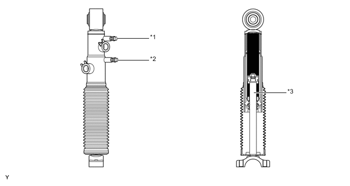
Text in Illustration (Rear Stabilizer Control Cylinder) *1 Bleeder Port (for Upper Chamber) *2 Bleeder Port (for Lower Chamber) *3 Piston - -
-
-
Stabilizer Control with Accumulator Housing Assembly
-
The stabilizer control with accumulator housing assembly consists of 2 accumulators, 1 accumulator pressure sensor and 2 stabilizer control solenoid valves. Also, a service valve and a shutter valve used for filling fluid are located in the stabilizer control with accumulator housing assembly.
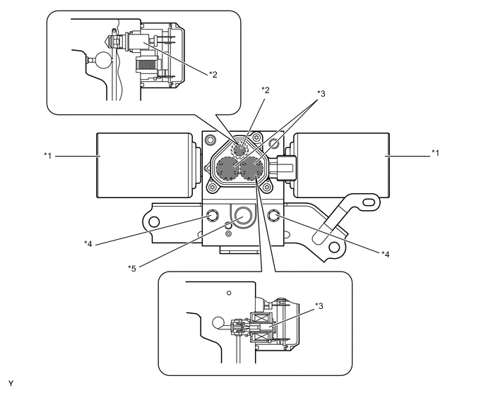
Text in Illustration *1 Accumulator *2 Accumulator Pressure Sensor *3 Stabilizer Control Solenoid Valve *4 Shutter Valve *5 Service Valve - - -
The metallic bellows type accumulator is used to enhance the gastight performance. The nitrogen gas filling the accumulator produces the initial pressure inside the system and absorbs the pressure from the stabilizer control cylinder, and the fluid volume also varies in accordance with the temperature, thus contributing to an increase in the riding comfort.

Text in Illustration *1 Metallic Bellows - - 
Fluid Chamber 
Gas Chamber (Nitrogen Gas)
-
-
-
OPERATION
-
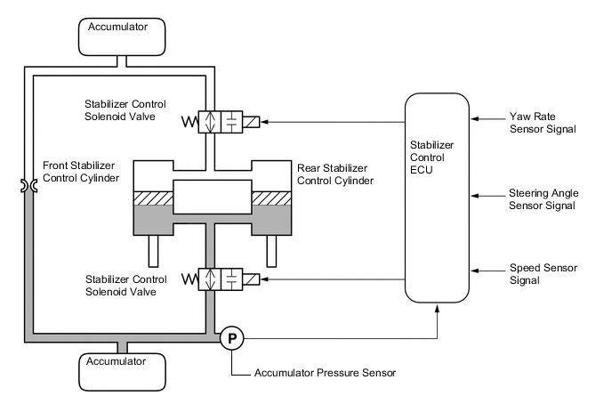
In accordance with the vehicle speed signal and the signals received from the steering angle sensor and yaw rate sensor assembly, the stabilizer control ECU controls the 2 stabilizer control solenoid valves in order to switch the hydraulic circuit in the system.
-
The 2 stabilizer control solenoid valves are controlled with the same timing and in the same direction.
-
While driving at a low speed, the stabilizer control solenoid valve is off and the oil passage between the chamber and accumulator is open.
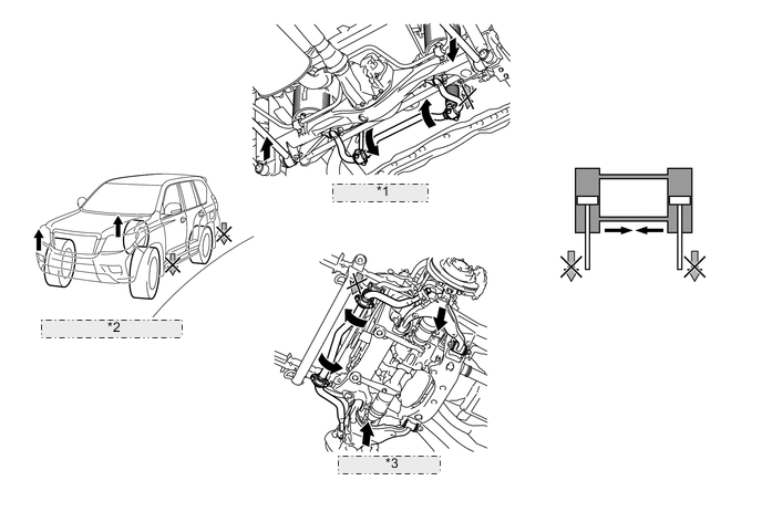
*1 Rear Suspension *2 During On-road Driving *3 Front Suspension 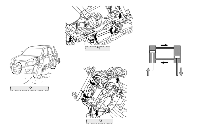
*1 Rear Suspension *2 During Off-road Driving *3 Front Suspension
-
-
FAIL-SAFE
-
If a malfunction occurs in any of the sensors or actuators, the stabilizer control ECU prohibits the system control.
-
-
DIAGNOSIS
-
If the stabilizer control ECU detects a malfunction in the KDSS, it illuminates the KDSS indicator light in the combination meter assembly to alert the driver of the malfunction.
-
The stabilizer control ECU will also store a Diagnostic Trouble Code (DTC). The DTC can be accessed through the use of a Global TechStream (GTS). For details, refer to the Repair Manual.
-