MANUAL TRANSMISSION SYSTEM
-
CONSTRUCTION
-
Gear Train
-
The transmission synchromesh mechanism is an all-speed constant mesh type.
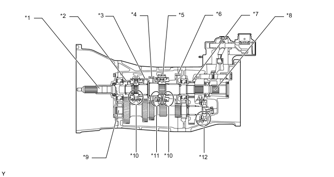
Text in Illustration *1 Input Shaft *2 4th Gear *3 3rd Gear *4 2nd Gear *5 Reverse Gear *6 1st Gear *7 5th Gear *8 Output Shaft *9 Counter Shaft *10 Single-cone Type Synchromesh Mechanism *11 Triple-cone Type Synchromesh Mechanism *12 Reverse Synchromesh Mechanism Synchromesh Mechanism Gear 1st 2nd 3rd, 4th and 5th Reverse Synchromesh Mechanism Type Single-cone Triple-cone Single-cone Reverse
-
-
Reverse Synchromesh Mechanism
-
The reverse synchromesh mechanism consists of 2 shifting keys, a shifting key spring, and a shifting key return spring.
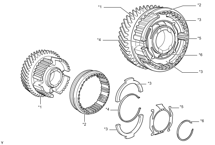
Text in Illustration *1 Counter 5th Gear *2 Hub Sleeve *3 Shifting Key *4 Shifting Key Spring *5 Shifting Key Return Spring *6 Snap Ring
-
-
-
OPERATION
-
Reverse Synchromesh Mechanism
-
While shifting into 5th, the 2 shifting keys move in unison with the hub sleeve (F1). With "A" acting as the fulcrum, the 2 shifting keys move to push the synchronizer ring only for the amount of the lever ratio (F2). The shift effort can be reduced only by this amount.
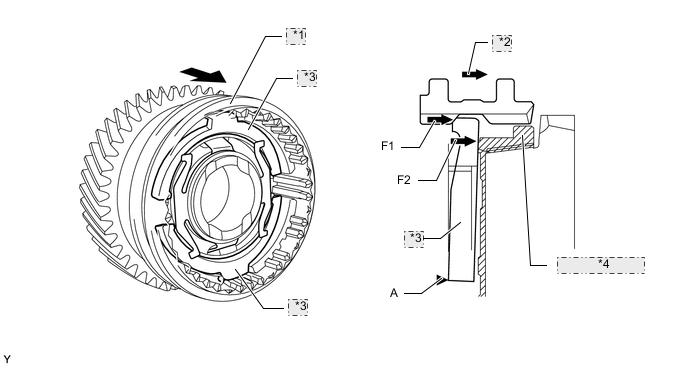
*1 Hub Sleeve *2 Hub Sleeve Moving Direction *3 Shifting Key *4 Synchronizer Ring -
While shifting into reverse, with "B" acting as the fulcrum, the 2 shifting keys move to push the synchronizer ring (F2). As a result, a brake is applied to the rotation of the counter shaft and gear noise is prevented.
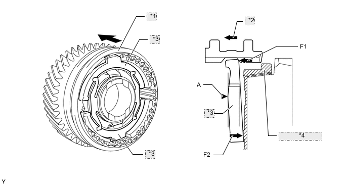
*1 Hub Sleeve *2 Hub Sleeve Moving Direction *3 Shifting Key *4 Synchronizer Ring
-
-