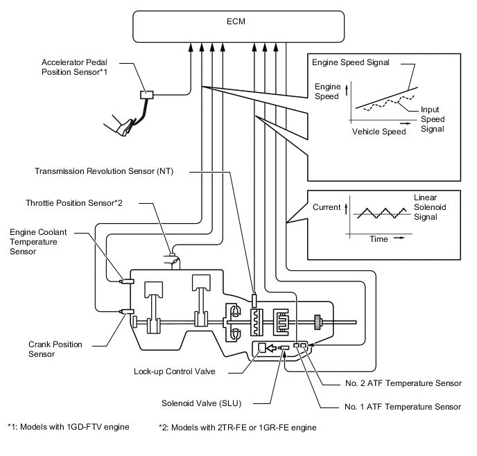
AUTOMATIC TRANSMISSION SYSTEM
-
FUNCTION OF MAIN COMPONENTS
Component Function Torque Converter Assembly
-
Transmits the engine power to the transmission.
-
Increases engine torque.
Oil Pump Provides oil pressure necessary for transmission operation. No. 1 Clutch (C1) Connects the input shaft and the intermediate shaft. No. 2 Clutch (C2) Connects the input shaft and the center planetary gear assembly. No. 1 Brake (B1) Locks the rotations of the front planetary carrier and the center planetary ring gear. No. 2 Brake (B2) Locks the rotation of the rear planetary ring gear. No. 3 Brake (B3) Locks the rotation of the front planetary ring gear. 1-way Clutch (F) Locks the counterclockwise rotations of the center planetary carrier and the rear planetary ring gear. Planetary Gears Change the power transmission route in accordance with clutch and brake operation, and increase or decrease output shaft revolution accordingly. Solenoid Valve (SL1) Performs shift controls. Solenoid Valve (SL2) Performs shift controls. Solenoid Valve (SL3) Performs shift controls. Solenoid Valve (SL4) Performs shift controls. Solenoid Valve (SLT) Controls line pressure. Solenoid Valve (SLU)
-
Performs lock-up clutch controls.
-
Performs B2 brake hydraulic pressure controls (only for the 1st range when the S mode is selected).
Solenoid Valve (SL) Shifts between lock-up hydraulic pressure and B2 brake hydraulic pressure. No. 1 ATF Temperature Sensor Detects the ATF temperature. No. 2 ATF Temperature Sensor Detects the ATF temperature. Transmission Revolution Sensor (NT) Detects the input speed of the transmission. Transmission Revolution Sensor (SP2) Detects the output speed of the transmission. Park/Neutral Position Switch Assembly Detects the shift lever position (P, R, N, D). Transmission Control Switch
-
Detects that the shift lever is in S.
-
Detects the driver's upshift and downshift operations when the shift lever is in S.
2nd Start Switch (Pattern Select Switch Assembly) Sends a 2nd start mode signal to the ECM. Drive Mode Select*1
-
Outputs the NORMAL, SPORT*2 or SPORT S/S+*3 mode signal to the ECM when operated by the driver.
-
Outputs the ECO mode signal to the ECM via the air conditioning amplifier assembly when operated by the driver.
Combination Meter Assembly Shift Display
-
Indicates the shift lever position.
-
Indicates to inform the driver of driving in D mode or S mode.
-
Indicates the shift range (S1 to S6).
MIL Illuminates or blinks to inform the driver when the ECM detects a malfunction. 2nd Start Indicator Light Illuminates when the driver selects the 2nd start mode. ATF Temperature Warning Light*4 Warns the driver by lighting up when the ATF is at a high temperature. Multi-information Display*5
-
Warns the driver by displaying a message when the ATF is at a high temperature.
-
Displays a Diagnostic Trouble Code (DTC).
Master Warning Light*5 Warns the driver by lighting up when a message is shown on the multi-information display. Buzzer
-
Sounds when shift-down operation is rejected in S mode.
-
Warns the driver by sounding when a message is shown on the multi-information display.*5
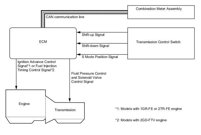
ECM
-
Controls each solenoid valve and engine output in response to signals from each sensor and switch.
-
When the ECM detects a malfunction, it makes a diagnosis and memorizes the failed section.
4WD Control ECU Sends a drive mode signal to the ECM. Air Conditioning Amplifier Assembly Sends a shift-up tardiness control signal to the ECM. Driving Support ECU Assembly*6 Sends a shifting control request signal to the ECM. Tech Tips
*1: Models with drive mode select
*2: Models without AVS
*3: Models with AVS
*4: Models with analog display type combination meter assembly
*5: Models with Optitron display type combination meter assembly
*6: Models with dynamic radar cruise control system
-
-
SYSTEM CONTROL
Electronic Control of Automatic Transmission Control Function Powertrain Cooperative Control Controls both the shift control and engine output control in an integrated way, thus achieving excellent shift characteristics and driveability. Shift Timing Control The ECM sends current to solenoid valves (SL1), (SL2), (SL3), (SL4) and/or (SL) based on signals from various sensors in order to shift the gears. Line Pressure Control Actuates the solenoid valve (SLT) to control the line pressure in accordance with information from the ECM and the operating conditions of the transmission. Clutch Pressure Optimal Control The solenoid valves (SL1), (SL2), (SL3), (SL4), (SLT) and (SLU) minutely control the clutch pressure in accordance with the engine output and driving conditions of the transmission. Clutch to Clutch Pressure Control By utilizing pressure output from solenoid valves (SL1), (SL2), (SL3) and (SL4) based on drive signals sent from the ECM, each of the clutch and brake hydraulic pressures can be controlled directly and independently. Vehicle Lift Control The clutch release speed has been optimized to restrain the upward movement of the vehicle when the shift lever is moved from D to N. Shift Down Control The hydraulic passages and control have been optimized in order to ensure a smooth shift feel during downshifting to accelerate the vehicle. Engine Torque Control Retards the engine ignition timing*1 or fuel injection volume*2 temporarily to improve shift feeling while upshifts or downshifts occur. Lock-up Timing Control The ECM sends current to the solenoid valve (SLU) based on signals from various sensors and engages or disengages the lock-up clutch. Flex Lock-up Clutch Control Controls the solenoid valve (SLU), provides an intermediate mode for when the lockup clutch is between on and off, and increases the operating range of the lock-up clutch to improve fuel economy. Coast Downshift Control The ECM performs downshifts before fuel cut ends to prevent the engine speed from decreasing and maintain the fuel cut. Artificial Intelligence-shift Control (AI-shift Control) Based on the signals from various sensors, the ECM determines the road conditions and the intention of the driver. Thus, an appropriate shift pattern is automatically determined, which improves driveability. Multi-mode Automatic Transmission The ECM appropriately controls the automatic transmission in accordance with the shift range position selected while the shift lever is in S. Drive Mode Select*3 Makes it possible to select the driving mode by performing switch operations. ATF High Temperature Control When the ATF is at a high temperature, normal shifting characteristics will be changed to shifting characteristics which actively utilize the low gear range to prevent the oil temperature from rising further. Tech Tips
*1: Models with 2TR-FE or 1GR-FE engine
*2: Models with 1GD-FTV engine
*3: Models with drive mode select
-
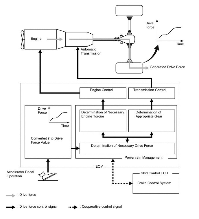
Powertrain Cooperative Control
-
The Driving Response and Acceleration Management System (DRAMS) is used for this model. This system integrally controls the engine, transmission and other driving related controls in order to improve vehicle maneuverability and driving comfort, as well as provide optimal drive feeling as a whole, including the behavior of the vehicle, while taking into account the drivers' needs and environment.
-
By integrally controlling the engine and automatic transmission using this system, acceleration maneuvers are replaced with drive force demanded by the driver. As a result, quick response and a high quality driving experience in accordance with the driver's intentions is achieved, such as when accelerating or decelerating, starting or stopping, or during gear shifts to provide demanded drive force while still producing a smoother shift transition.
-
Start Control (Models with 2TR-FE or 1GR-FE Engine)
-
With DRAMS, engine torque will optimally be controlled in a real-time manner in accordance with speed ratios between engine speed and turbine speed so that finely controlled starting capability has been provided while balancing the "reduction of a feel of jump and suppression of tire slipping" and "smooth responsiveness" when starting.
-
-
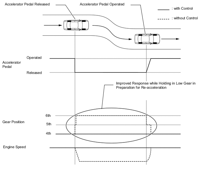
Integrated Drive Force Control (Models with 2TR-FE Engine)
-
By increasing drive force before making a downshift when accelerating, a feel of slowness after downshifting has been reduced, making it possible to balance smooth shift characteristic and responsiveness when accelerating.
-
-
-
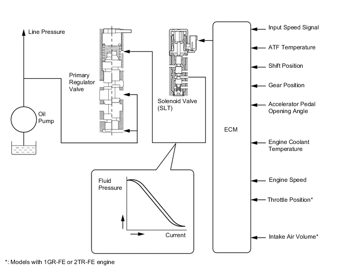
Line Pressure Control
-
In order to obtain predetermined line pressure characteristics in accordance with each sensor signal, the ECM activates the solenoid valve (SLT) to regulate the throttle pressure.
-
This makes it possible for the primary regulator valve to precisely and minutely control the line pressure in accordance with the engine output, thus providing smoother shift characteristics.
-
-
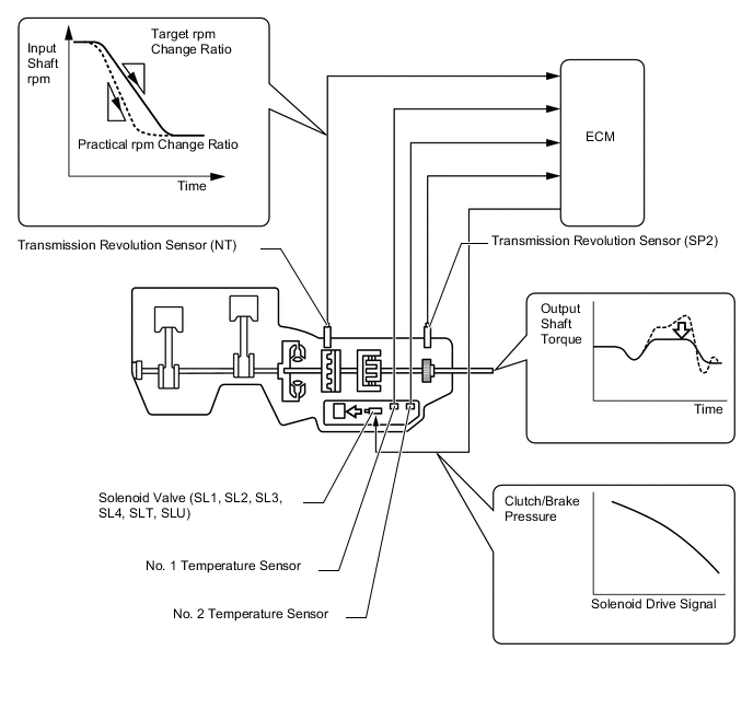
Clutch Pressure Optimal Control
-
The ECM monitors the signals from various types of sensors, such as the transmission revolution sensor (NT), allowing solenoid valves (SL1), (SL2), (SL3), (SL4), (SLT) and (SLU) to minutely control the clutch pressure in accordance with engine output and driving conditions. As a result, smooth shift characteristics are achieved.
-
-
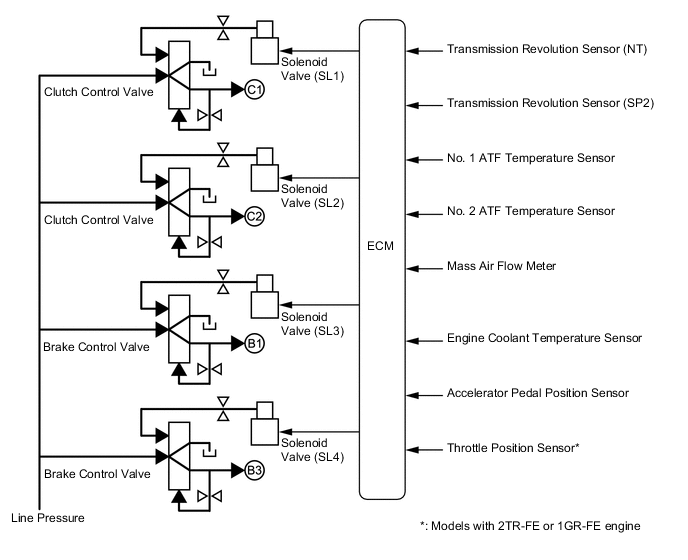
Clutch to Clutch Pressure Control
-
By using a clutch to clutch pressure control without using 1-way clutches in the 2nd or higher gears, a light, compact 6-speed automatic transmission has been provided.
-
By utilizing pressure output from solenoid valves (SL1), (SL2), (SL3) and (SL4) based on drive signals sent from the ECM, each of the clutch and brake hydraulic pressures can be controlled directly and independently.
-
-
Lock-up Timing Control
-
The ECM operates the lock-up timing control in order to improve fuel economy.
Lock-up Timing Control Operation Gear Position Shift Lever Position or Shift Range D, S6 S5 S4 1st X X X 2nd X X X 3rd X X X 4th ○ ○ ○ 5th ○ ○ - 6th ○ - - Tech Tips
○: Available
X: Does not operate
-: Not applicable
-
-
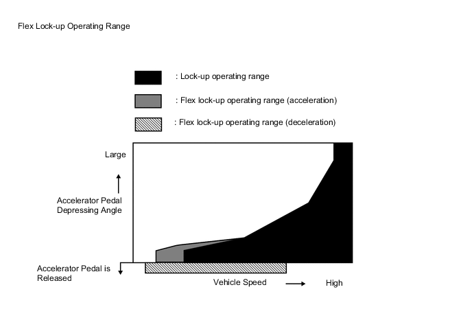
Flex Lock-up Clutch Control
-
During acceleration, partial control of the power transmission between the lock-up clutch and torque converter greatly boosts transmission efficiency in accordance with the driving conditions, improving fuel economy.
-
Even when the vehicle is decelerating (the accelerator pedal is released), flex lock-up clutch control operates. As a result, the fuel cut area is expanded and fuel economy is improved.
-
By allowing flex lock-up clutch control to continue operating during gearshifts, smooth torque transmission is obtained. As a result, fuel economy and driveability are improved.
-
For flex lock-up clutch control, H infinity (H∞) control theory is used to achieve a high level of system stability and response to various characteristic changes.
Flex Lock-up Clutch Control Operation (Acceleration) Gear Position Shift Lever Position or Shift Range D, S6 S5 S4 1st X X X 2nd X X X 3rd X X X 4th ○ ○ ○ 5th ○ ○ - 6th ○ - - Tech Tips
○: Operates
X: Does not operate
-: Not applicable
Flex Lock-up Clutch Control Operation (Deceleration) Gear Position Shift Lever Position or Shift Range D, S6 S5 S4 1st X X X 2nd X X X 3rd X X X 4th ○ ○ X 5th ○ ○ - 6th ○ - - Tech Tips
○: Operates
X: Does not operate
-: Not applicable
-
-
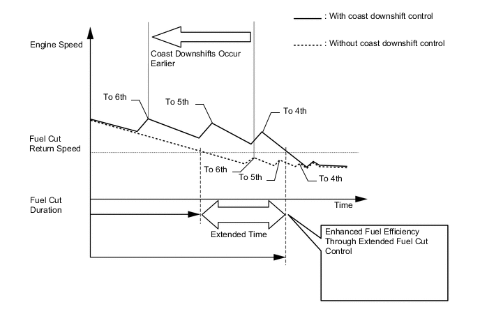
Coast Downshift Control
-
Downshift control is used when decelerating, allowing for low fuel consumption by extending fuel cut control as much as possible.
-
By performing flex lock-up control and downshift control at the same time when decelerating, a decrease of engine speed has been suppressed, while extending fuel cut control as much as possible without lowering the engine speed below the fuel cut recovery speed.
-
By expanding operating gears and widening operating areas through close-gear ratios, fuel efficiency has significantly been enhanced and drivability has been improved by optimizing deceleration force when controls are activated.
-
-
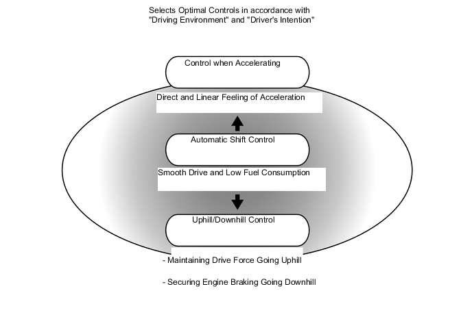
Artificial Intelligence-shift Control (AI-shift Control)
-
AI-shift control selects optimal controls in accordance with "driving environment" and the "driver's intention" based on the degree of accelerator opening, vehicle speed, brake signals, etc.
-
Smooth driving and low fuel consumption have been achieved while driving normally. A strong and linear feeling of acceleration has been provided when accelerating. A direct feeling of deceleration through engine braking and high fuel efficiency have been achieved when decelerating.
-
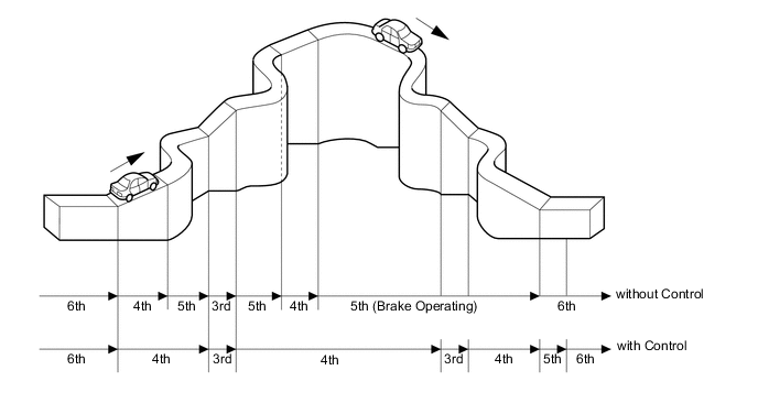
Under road condition support control, the ECM identifies the throttle valve opening angle, accelerator pedal opening angle and vehicle speed to determine whether the vehicle is being driven uphill or downhill. Unnecessary upshifting is restrained to automatically achieve optimal drive force at all times while driving uphill. Downshifting is automatically conducted to achieve optimal engine brake force while driving downhill.
-
On models with the 2TR-FE engine, higher gear settings have been added for high speed gears (5th and 6th gears). In order to balance the reduction of additional drive force and the improvement of fuel efficiency when driving at high speeds, a high speed gear effective utilization control is used.
-
By calculating the maximum additional drive force to be generated at high speed gears in a real-time manner, as well as determining the availability of high speed gears according to driving conditions (running resistance, driver's acceleration maneuvers), "balanced, improved fuel efficiency and driving capability" have been achieved.
-
Conditions Determining that Running in 6th Gear is Impossible (Examples)
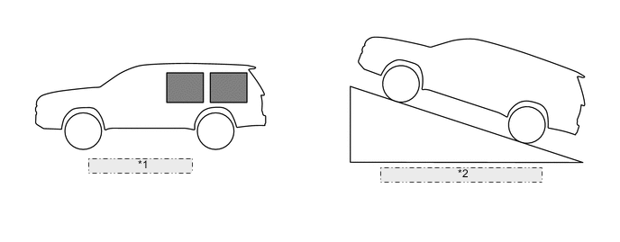
*1 Heavy Load: 5th Gear *2 Accelerating on Slope: 5th Gear -
Conditions Determining that Running in 6th Gear is Possible
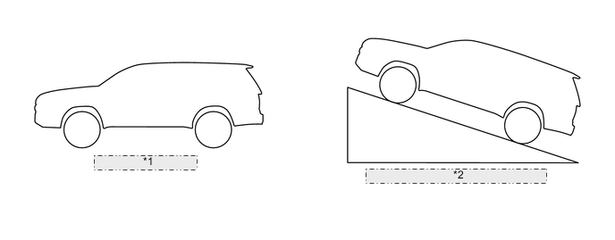
*1 Light Load: 6th Gear *2 Constant Driving on Slope: 6th Gear
-
-
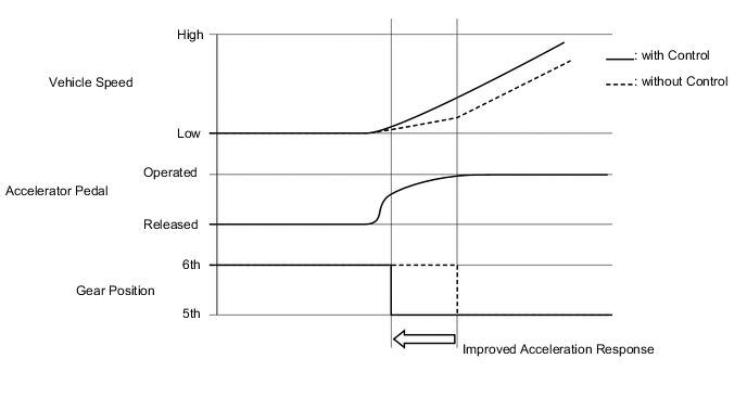
Sudden Accelerator Pedal Release Control (Models with 1GD-FTV or 1GR-FE Engine)
When the accelerator pedal is released suddenly, the transmission is kept in gear as long as possible, which improves engine braking force.
-
Sudden Accelerator Pedal Depress Control (Models with 1GD-FTV or 1GR-FE Engine)
When the accelerator pedal is depressed suddenly, downshifting occurs earlier ensuring improved acceleration response.
-
-
Multi-mode Automatic Transmission
-
The driver can select the desired gear step by moving the shift lever "+" (forward) or to "-" (backward) while the shift lever is in S (6-speed sequential shiftmatic mode). Thus, the driver is able to change gear steps with a manual-like feel.
-
6-speed sequential shiftmatic mode can be selected from normal driving mode by moving the shift lever to S. The driver can change the gear step by selecting it using the shift lever.
-
The driver selects S mode by moving the shift lever to S. At this time, the S4 or S5 range is selected in accordance with the vehicle speed.
-
The ECM will restrict the changing of the shift range if it detects a malfunction in the automatic transmission system.
-
If the vehicle speed and engine speed exceed or go below a preset level in response to the driver's downshift operation request, changing the shift range will be prohibited. In this case, the buzzer in the combination meter will sound to alert the driver.
-
The shift lever position and the shift range are indicated by the shift display in the combination meter assembly.
-
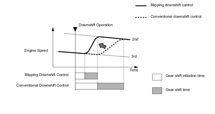
Blipping downshift control is used to improve shift change response and shift feeling in 6- speed sequential shiftmatic mode.
-
The blipping downshift control regulates each clutch and brake using the clutch to clutch pressure control, allowing them to be engaged smoothly and disengaged quickly. In addition, engine speed is boosted by powertrain cooperative control, thus ensuring engine brake force. In this way, a smooth and quick downshift is achieved. In addition, quicker downshifting has been made available by directly controlling clutch pressure.
Tech Tips
If ATF and engine coolant temperatures are low, the shift change response will be the same as when blipping downshift control is not available.
-
-
-
FUNCTION
-
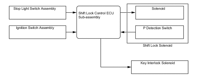
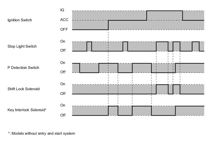
Shift Lock System
-
The shift lock system prevents the shift lever from being moved to any position other than P, unless the ignition switch is ON and the brake pedal is depressed. This prevents the vehicle from starting off suddenly.
-
The shift lock system prevents the shift lever from being moved to any position other than P, unless the ignition switch is ON and the brake pedal is depressed. This prevents the vehicle from starting off suddenly.
*: Models without entry and start system
-
The key interlock function prevents the key from being pulled out after the ignition switch has been turned off, unless the shift lever has been moved to P. Thus, the driver is urged to park the vehicle with the shift lever in P.
-
A shift lock release button, which manually overrides the shift lock mechanism, is used.
-
Models with Entry and Start System
-
Models without Entry and Start System
-
-
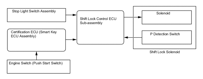
The shift lock control ECU sub-assembly uses the P detection switch to detect the shift lever position, and receives input signals from the stop light switch assembly and ignition switch. Upon receiving these signals, the shift lock control ECU sub-assembly turns on the shift lock solenoid and key interlock solenoid in order to release the shift lock and key interlock.
-
-
2nd Start Mode
-
2nd start mode can be selected to make smooth starting off possible on surfaces with low friction coefficients, such as snow-covered roads.
-
When the 2nd start mode is selected while the shift lever is in D or in the S6, S5, S4, S3 or S2 range, the vehicle can start in the 2nd gear. After a start, if the shift lever is in D or in the S6, S5, S4 or S3 range, transmission will shift up automatically into 3rd, 4th, 5th or overdrive gears in the normal manner. If the shift lever is in the S2 range, the transmission will continue to operate in the 2nd gear.
-
-
Drive Mode Select (Models with Drive Mode Select)
-
The motive force characteristics for the accelerator opening angle can be changed through the selection of the drive mode according to driver preference.
-
An indicator is provided in the combination meter assembly and the drive mode the driver selected can be recognized.
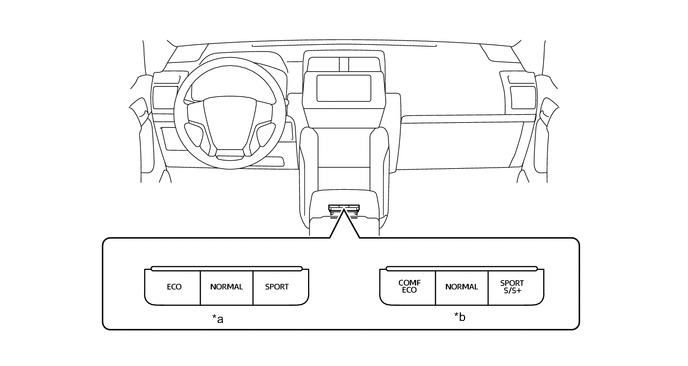
*a Models without AVS *b Models with AVS Drive Mode Powertrain Control Mode Outline NORMAL Mode
COMF Mode*1
Normal This drive mode provides optimum driveability. ECO Mode Eco The ECM optimizes fuel economy and driving performance by gradually generating the motive force in comparison to the accelerator pedal operation. At the same time, the ECM supports eco driving by optimizing air conditioning performance. SPORT Mode*2
SPORT S/S+ Mode*1
Power The ECM controls motive force in the intermediate area of the accelerator pedal opening to a greater degree than that of NORMAL mode, improving acceleration performance. In addition, engine speed response performance has been improved in the high area of the accelerator pedal opening, thus producing a sporty drive. *1: Models with AVS
*2: Models without AVS
Tech Tips
When the transfer is in L4F or L4L, drive mode select cannot be used.
When 2nd start mode is selected, powertrain control is performed according to 2nd start mode.
-
-
-
CONSTRUCTION
-
Torque Converter
-
A compact, lightweight and high-capacity torque converter assembly is used. The torque converter supports lock-up clutch control, thus improving fuel economy.
-
Laser welding has been used for the outer periphery of the torque convertor to suppress welding distortion and stabilize flex lock-up clutch control.
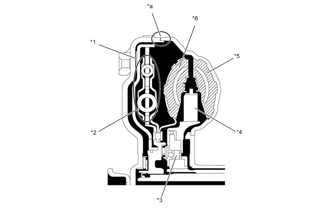
Text in Illustration *1 Lock-up Clutch *2 Lock-up Damper *3 1-way Clutch *4 Stator *5 Pump Impeller *6 Turbine Runner *a Laser Welded Portion - -
-
-
Oil Pump
-
The oil pump is operated by the torque converter assembly. The oil pump lubricates the planetary gear units and supplies operating fluid pressure for hydraulic control. The front oil pump drive gear is continually driven by the engine via the pump impeller. The pump has sufficient capacity to supply the necessary fluid pressure throughout all speed ranges, as well as in reverse.
Text in Illustration *1 Front Oil Pump Body Sub-assembly *2 Front Oil Pump Driven Gear *3 Stator Shaft Assembly *4 Oil Pump Cover *5 Front Oil Pump Drive Gear - -
-
-
ATF Cooling System
-
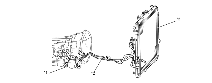
A water-cooled type ATF cooler built into the radiator is used on the models with 2TR-FE or 1GD-FTV engine.
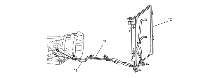
Text in Illustration (Models with 2TR-FE Engine) *1 Oil Cooler Inlet Tube Sub-assembly *2 Radiator Assembly *3 Oil Cooler Outlet Tube Sub-assembly - - 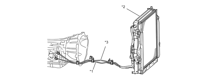
Text in Illustration (Models with 1GD-FTV Engine) *1 Oil Cooler Inlet Tube Sub-assembly *2 Radiator Assembly *3 Oil Cooler Outlet Tube Sub-assembly - - -
A water-cooled type ATF cooler and air-cooled type ATF cooler are used on all models excluding models for Europe or Chile with 1GR-FE engine.
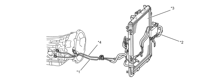
Text in Illustration (except Models for Europe or Chile with 1GR-FE Engine) *1 Oil Cooler Inlet Tube Sub-assembly *2 Oil Cooler Assembly *3 Radiator Assembly *4 Oil Cooler Outlet Tube Sub-assembly -
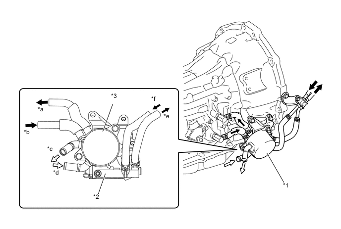
A water-cooled type ATF cooler and ATF warmer (transmission oil cooler with thermostat assembly) are used on the models for Europe or Chile with 1GR-FE engine.
Text in Illustration (Models for Europe or Chile with 1GR-FE Engine) *1 ATF Warmer (Transmission Oil Cooler with Thermostat Assembly) *2 Oil Cooler Tube Sub-assembly *3 Radiator Assembly - - -
The ATF warmer (transmission oil cooler with thermostat assembly) uses engine coolant that has been warmed by the engine to warm up the ATF quickly. Consequently, the friction losses of the automatic transmission are quickly reduced, thus improving fuel economy.
-
The ATF warmer (transmission oil cooler with thermostat assembly) has a thermostat that changes the route through which the ATF flows.
Text in Illustration *1 Transmission Oil Cooler with Thermostat Assembly *2 Thermostat *3 Transmission Oil Cooler - - *a To Transmission *b From Transmission *c To Engine *d From Heater Core *e To Radiator *f From Radiator 
ATF Flow 
Engine Coolant Flow -
When the ATF temperature is low, it is heated by the ATF warmer (transmission oil cooler with thermostat assembly) using the engine coolant, and when the ATF temperature is high, it is cooled down by the ATF warmer (transmission oil cooler with thermostat assembly) and radiator (water-cooled type ATF cooler).
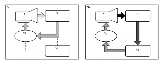
Text in Illustration *1 Transmission *2 ATF Warmer (Transmission Oil Cooler with Thermostat Assembly) *3 Thermostat *4 Radiator (Water-cooled Type ATF Cooler) *a ATF Temperature is Low *b ATF Temperature is High -
The thermostat consists of a poppet valve, a bypass valve and an element case (contains wax). When the ATF temperature changes from low to high, the wax will expand to start to open the poppet valve and close the bypass valve, thus switching the ATF passages.
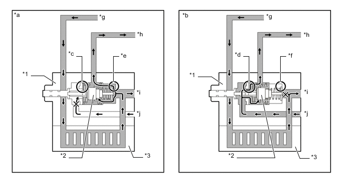
Text in Illustration *1 Thermostat *2 Element Case (Contains Wax) *3 ATF Warmer (Transmission Oil Cooler with Thermostat Assembly) - - *a ATF Temperature is Low *b ATF Temperature is High *c Poppet Valve: Closed *d Poppet Valve: Open *e Bypass Valve: Openv *f Bypass Valve: Closed *g From Transmission *h To Transmission *i To Radiator (Water-cooled Type ATF Cooler) *j From Radiator (Water-cooled Type ATF Cooler) ATF Flow - -
-
-
ATF Filling Procedures
-
An ATF filling procedure is used in order to improve the accuracy of the ATF level when the transmission is being repaired or replaced. As a result, the oil filler tube and the oil level gauge used in the conventional automatic transmission have been discontinued, eliminating the need to inspect the fluid level as a part of routine maintenance. For details about the ATF filling procedures, refer to the Repair Manual.
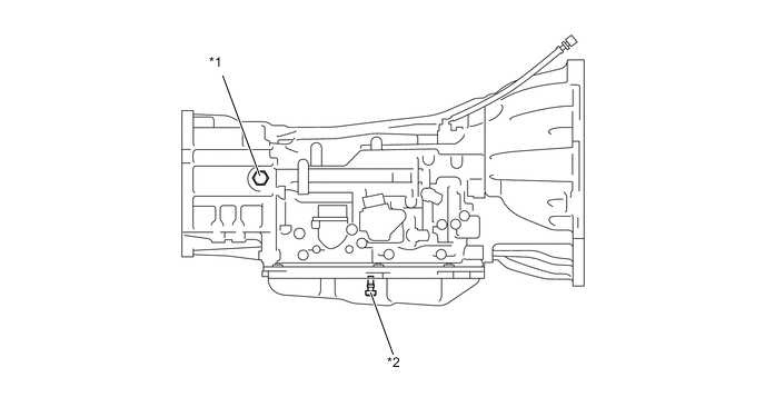
Text in Illustration *1 Refill Plug *2 Overflow Plug
-
-
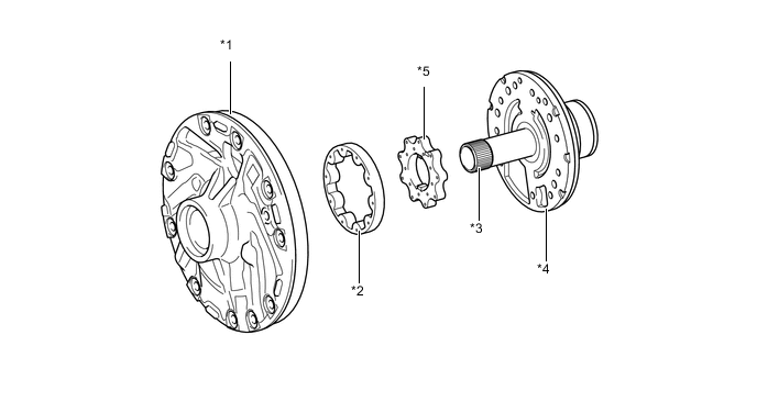
Planetary Gear Unit
-
The gear train consists of 2 multi-plate clutches, 3 multi-plate brakes, a 1-way clutch and 3 sets of planetary gears, each consisting of a sun gear, a pinion gear and a ring gear.
Text in Illustration *1 No. 2 Clutch (C2) *2 No. 1 Clutch (C1) *3 Front Planetary Gear Assembly *4 Center Planetary Gear Assembly *5 Intermediate Shaft *6 Rear Planetary Gear Assembly *7 No. 2 Brake (B2) *8 1-way Clutch Assembly *9 No. 3 Brake (B3) *10 No. 1 Brake (B1) 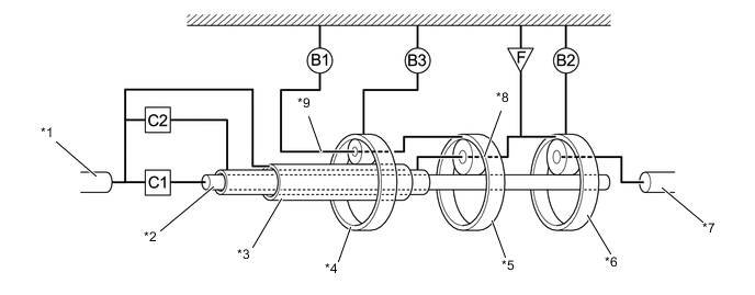
Text in Illustration *1 Input Shaft *2 Intermediate Shaft *3 Front Planetary Sun Gear *4 Front Planetary Gear Assembly *5 Center Planetary Gear Assembly *6 Rear Planetary Gear Assembly *7 Output Shaft *8 Center Planetary Carrier *9 Front Planetary Carrier - -
-
-
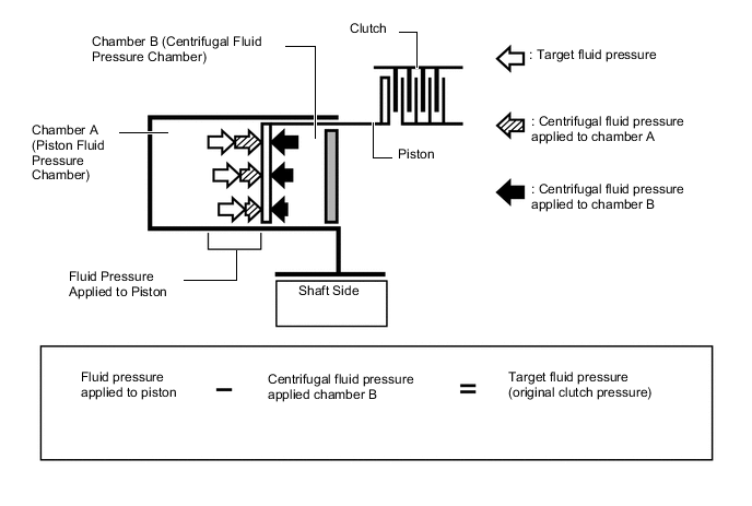
Centrifugal Fluid Pressure Canceling Mechanism
-
A centrifugal fluid pressure canceling mechanism is used on the C1 and C2 clutches that are applied when shifting 3rd-4th and 4th-5th.
-
Clutch shifting operation is affected not only by the valve body controlling fluid pressure but also by centrifugal fluid pressure that is present due to fluid in the clutch piston oil pressure chamber. The centrifugal fluid pressure canceling mechanism uses chamber B to reduce the effect applied to chamber A. As a result, smooth shifting with excellent response has been achieved.
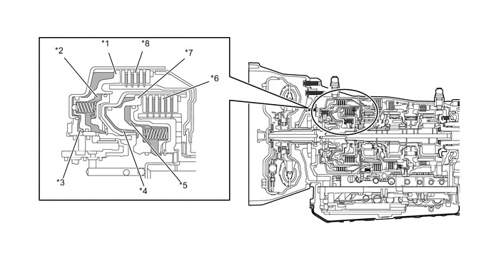
Text in Illustration *1 Piston (for C2) *2 Chamber B (for C2) *3 Chamber A (for C2) *4 Chamber A (for C1) *5 Chamber B (for C1) *6 No. 1 Clutch (C1) *7 Piston (for C1) *8 No. 2 Clutch (C2) -
Chamber B is filled by fluid supplied to the shaft for lubrication. As a result of filling chamber B, the same amount of fluid pressure is present on both sides of the piston due to centrifugal force. This cancels the effects of fluid pressure on the piston caused by centrifugal force. Accordingly, it is not necessary to discharge the fluid through the use of a check ball, and highly responsive and smooth shifting characteristics are achieved.
-
-
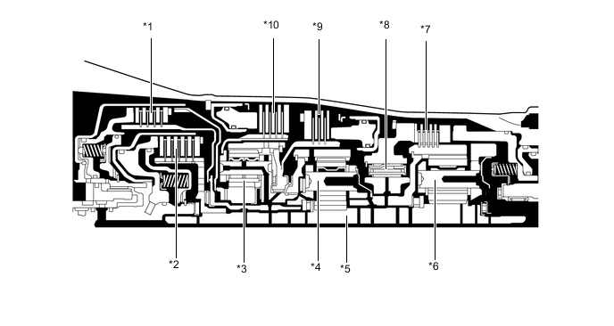
Transmission Valve Body Assembly
-
The transmission valve body assembly consists of upper and lower valve bodies and 7 solenoid valves.
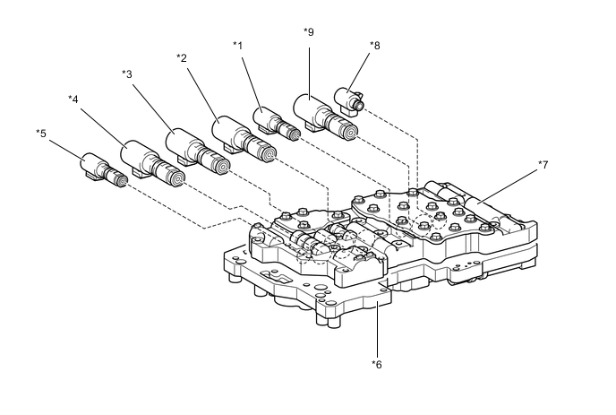
Text in Illustration *1 Solenoid valve (SLU) *2 Solenoid valve (SL3) *3 Solenoid valve (SL1) *4 Solenoid valve (SL2) *5 Solenoid valve (SLT) *6 Lower Valve Body *7 Upper Valve Body *8 Solenoid valve (SL) *9 Solenoid valve (SL4) - - 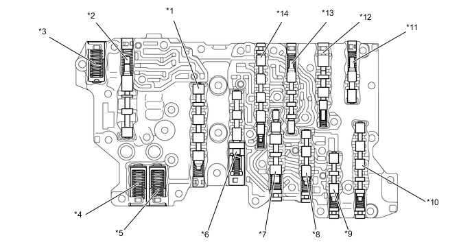
Text in Illustration (Upper Valve Body) *1 Lock-up Relay Valve *2 Secondary Regulator Valve *3 C2 Damper *4 SLT Damper *5 B2 Damper *6 Lock-up Control Valve *7 B4 Apply Control Valve *8 B4 Control Valve *9 B1, B4 Apply Control Valve *10 Solenoid Relay Valve *11 Solenoid Modulator Valve *12 B1 Apply Control Valve *13 Clutch Control Valve *14 Sequence Valve 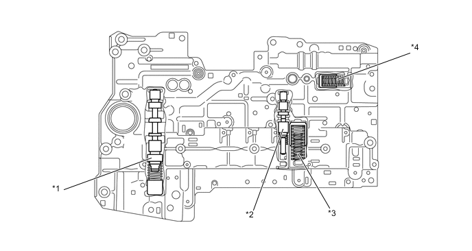
Text in Illustration (Lower Valve Body) *1 Primary Regulator Valve *2 B2 Apply Control Valve *3 C1 Accumulator *4 B1 Damper
-
-
Solenoid valves (SL1), (SL2), (SL3), (SL4), (SLT) and (SLU)
-
Solenoid valves have been provided for controlling clutch engagement hydraulic pressure (SL1, SL2), lock-up clutch (SLU), line hydraulic pressure (SLT), and brake engagement hydraulic pressure (SL3, SL4).
-
By directly controlling the hydraulic pressure for each clutch and brake with high flow rate solenoid valves (SL1), (SL2), (SL3), (SL4), shift-change responsiveness has been improved, shift shocks have been reduced, and the structure has been simplified through the reductions of oil passage lengths and the numbers of components.
-
Solenoid Valves (SL1), (SL2), (SL3) and (SL4)
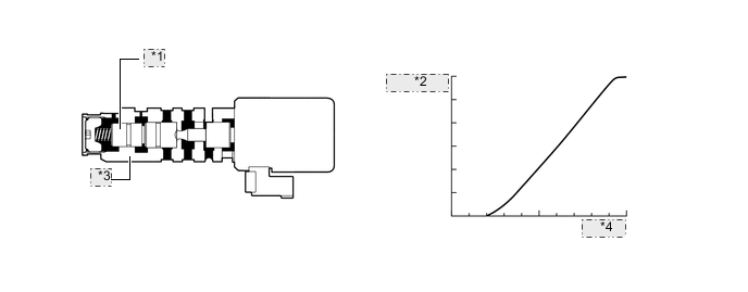
*1 Spool Valve *2 Hydraulic Pressure *3 Sleeve *4 Current -
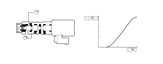
Solenoid Valve (SLT)
*1 Spool Valve *2 Hydraulic Pressure *3 Sleeve *4 Current -
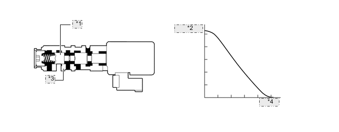
Solenoid Valve (SLU)
*1 Spool Valve *2 Hydraulic Pressure *3 Sleeve *4 Current
Function of Solenoid Valves Solenoid Valve Function Solenoid Valve (SL1) Performs shift controls. Solenoid Valve (SL2) Performs shift controls. Solenoid Valve (SL3) Performs shift controls. Solenoid Valve (SL4) Performs shift controls. Solenoid Valve (SLT) Performs line pressure controls. Solenoid Valve (SLU)
-
Performs lock-up clutch controls.
-
Performs B2 brake hydraulic pressure controls (only for the 1st range when the shift lever is in S).
-
-
-
Solenoid Valve (SL)
-
A transmission 3-way solenoid (SL) has been provided for switching lock-up hydraulic pressure and B2 brake hydraulic pressure.
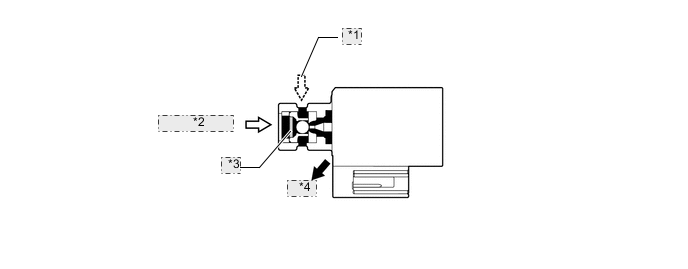
*1 Control Pressure *2 Line Pressure *3 Strainer *4 Drain Function of Solenoid Valve Solenoid Valve Function Solenoid Valve (SL) Shifts between lock-up hydraulic pressure and B2 brake hydraulic pressure.
-
-
ATF Temperature Sensor
-
The ATF temperature sensors are used for hydraulic pressure control. These sensors are used for revision of the pressure that is used to apply clutches and brakes in the transmission. This helps to ensure smooth shift quality.
Text in Illustration *1 No. 2 ATF Temperature Sensor *2 No. 1 ATF Temperature Sensor Engine Side - -
-
-
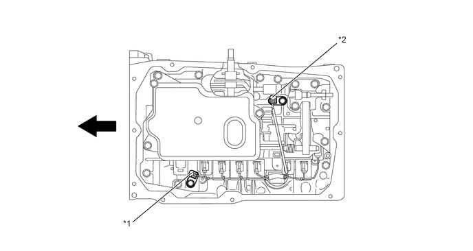
Park/Neutral Position Switch
-
The park/neutral position switch assembly sends the P, R, N, D and NSW signals to the ECM.
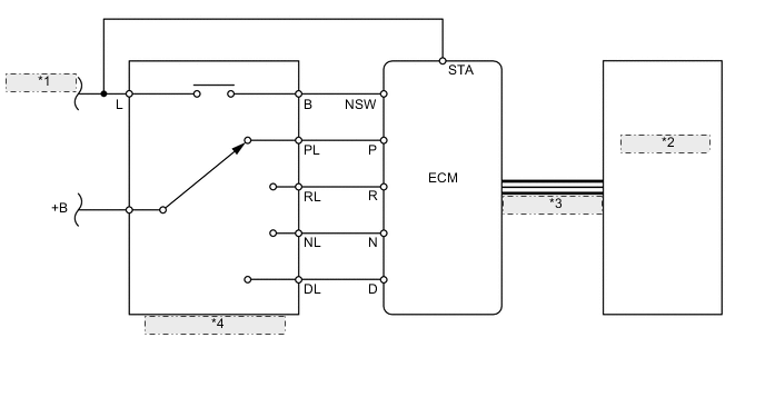
*1 To Starter Relay *2 Combination Meter Assembly *3 CAN communication line *4 Park/Neutral Position Switch Assembly
-
-
Transmission Control Switch
-
The transmission control switch is installed inside the transmission floor shift assembly to detect the S mode position and inform the ECM.
-
The transmission control switch detects whether the shift lever is in D or S, and detects the operating conditions of the shift lever ["+" (forward) or "-" (backward)] when the shift lever is in S, and sends signals to the ECM.
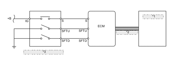
*1 Combination Meter Assembly *2 CAN communication line *3 Transmission Control Switch
-
-
Transmission Revolution Sensor
-
This automatic transmission uses a transmission revolution sensor (for NT signal) and a transmission revolution sensor (for SP2 signal). Thus, the ECM can detect the timing of the shifting of the gears and appropriately control the engine torque and hydraulic pressure in response to various conditions.
-
These transmission revolution sensors are the pick-up coil type.
-
The transmission revolution sensor (for NT signal) detects the input speed of the transmission. The direct clutch drum sub-assembly is used as the timing rotor for this sensor.
-
The transmission revolution sensor (for SP2 signal) detects the output speed of the transmission. The parking lock gear on the rear planetary gear is used as the timing rotor for this sensor.
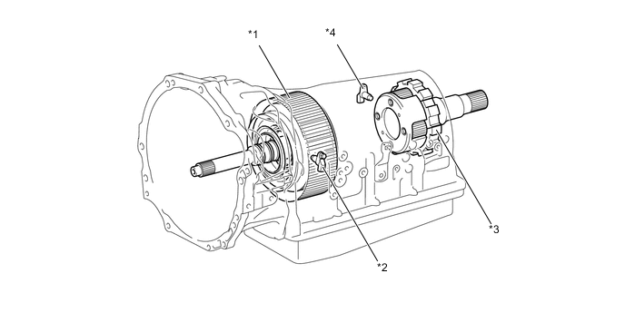
Text in Illustration *1 Direct Clutch Drum Sub-assembly *2 Transmission Revolution Sensor (NT) *3 Parking Lock Gear *4 Transmission Revolution Sensor (SP2)
-
-
Shift Control Mechanism
-
A gate type shift lever is used.
-
The shift control mechanism consists of a transmission floor shift assembly and a transmission control cable assembly.
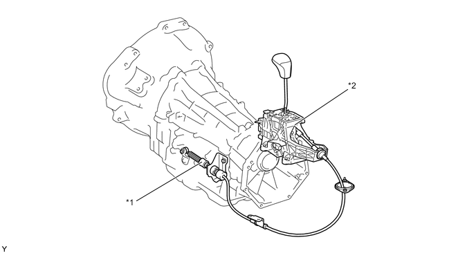
Text in Illustration *1 Transmission Control Cable Assembly *2 Transmission Floor Shift Assembly
-
-
-
OPERATION
-
Transmission Power Flow
Shift Position and Gear Position Shift Solenoid Valve SL1 SL2 SL3 SL4 SL SLU P - - - - - - R - - - ○ - - N - - - - - - D.S 1st ○ - - - - ● 2nd ○ - ○ - ○ - 3rd ○ - - ○ ○ - 4th ○ ○ - - ○ ○ 5th - ○ - ○ ○ ○ 6th - ○ ○ - ○ ○ Tech Tips
○: Operates
●: Operates during Engine Braking
Shift Position and Gear Position Clutch Brake 1-way Clutch C1 C2 B1 B2 B3 F1 P - - - - - - R - - - ○ ○ - N - - - - - - D.S 1st ○ - - ● - ○ 2nd ○ - ○ - - - 3rd ○ - - - ○ - 4th ○ ○ - - - - 5th - ○ - - ○ - 6th - ○ ○ - - - Tech Tips
○: Operates
●: Operates during Engine Braking
-
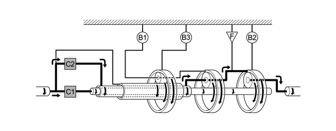
1st Gear (Shift Lever in D or S)
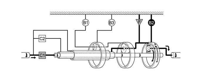
Text in Illustration 
Operates 
Operates during Engine Braking -
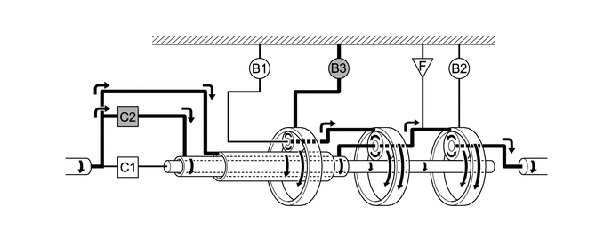
2nd Gear (Shift Lever in D or S)
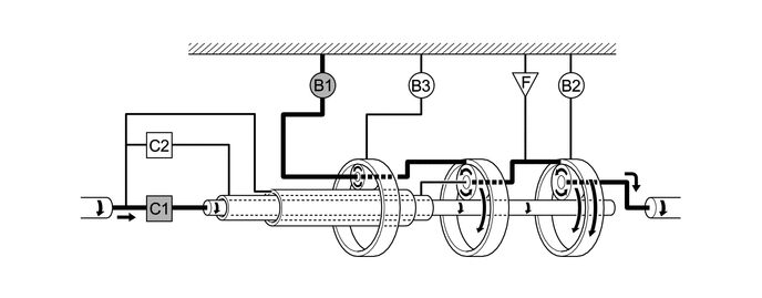
Text in Illustration Operates - - -
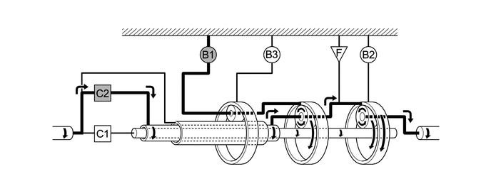
3rd Gear (Shift Lever in D or S)
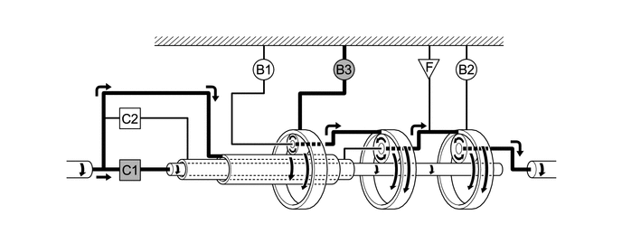
Text in Illustration Operates - - -
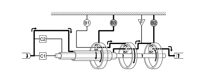
4th Gear (Shift Lever in D or S)
Text in Illustration Operates - - -
5th Gear (Shift Lever in D or S)
Text in Illustration Operates - - -
6th Gear (Shift Lever in D or S)
Text in Illustration Operates - - -
Reverse Gear (Shift Lever in R)
Text in Illustration Operates - -
-
-
-
FAIL-SAFE
-
The fail-safe function minimizes the loss of operability when an abnormality occurs in a sensor or a solenoid valve.
-
For details, refer to the Repair Manual.
-
-
DIAGNOSIS
-
When the ECM detects a malfunction, it makes a diagnosis and memorizes the failed section. Furthermore, the ECM illuminates or blinks the MIL in the combination meter assembly to inform the driver.
-
The ECM will also store the Diagnostic Trouble Codes (DTCs) of the malfunctions. The DTCs can be read by connecting a Global TechStream (GTS) to the DLC3.
-
For details, refer to the Repair Manual.
-