MANUAL TRANSMISSION SYSTEM
-
FUNCTION
-
Gear Shift Indicator (Models for Europe)
-
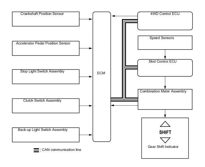
In the Gear Shift Indicator, the ECM calculates an environmentally favorable shift position based on the vehicle conditions, and makes a request to the combination meter assembly to indicate upshifting or downshifting. Then the Gear Shift Indicator in the combination meter gives a shifting recommendation to the driver.
-
The ECM determines the actual gear position based on the signals from the crankshaft position sensor and speed sensors, and the target gear position based on the signals from the accelerator pedal position sensor and speed sensors.
-
By driving in accordance with the shift change recommendations indicated by the Gear Shift Indicator, the driver can enhance, fuel economy and reduce exhaust gas output as much as possible.
-
The Gear Shift Indicator will not effect control while the vehicle is being driven in reverse.
-
The Gear Shift Indicator will not effect control while the vehicle is stopped or the clutch is not engaged while shifting.
-
The Gear Shift Indicator will not effect control while the transfer position switch in L4.
-
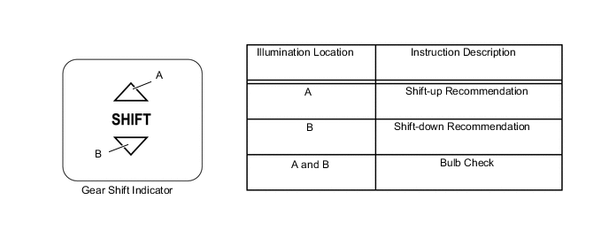
Upon receiving a shift instruction request from the ECM, the combination meter assembly will illuminate the Gear Shift Indicator.
-
The 2 indicator lights illuminate simultaneously during a bulb check.
-
-
-
CONSTRUCTION
-
Gear Train
-
The transmission synchromesh mechanism is an all-speed constant meshing type.
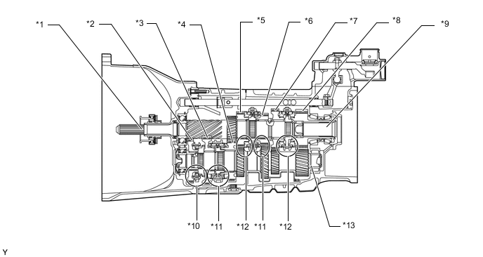
Text in Illustration *1 Input Shaft *2 Reverse Gear *3 1st Gear *4 2nd Gear *5 4th Gear *6 3rd Gear *7 6th Gear *8 5th Gear *9 Output Shaft *10 Reverse Type Synchromesh Mechanism *11 Triple-cone Type Synchromesh Mechanism *12 Single-cone Type Synchromesh Mechanism *13 Counter Shaft - - Synchromesh Mechanism Gear 1st, 2nd and 3rd 4th, 5th and 6th Reverse Synchromesh Mechanism Type Triple-cone Single-cone Reverse
-
-
Oil Separator
-
An oil separator made of aluminum alloy is provided at the bottom of the transmission rear case. This construction prevents the oil sump from being directly mixed by the counter shaft. By combining this with the transmission middle case, which has a tank construction, the oil mixing loss has been reduced.
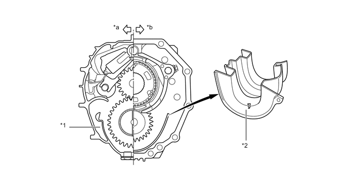
Text in Illustration *1 Tank Construction *2 Oil Separator *a Middle Case Side *b Rear Case Side
-
-
Shift and Select Mechanism
-
The shift and select mechanism has 4 shift forks and a sliding-shaft type shift. The shift detent mechanism that is used is the same as the conventionally used ball and spring detent system. High shifting characteristics have been obtained by providing a mechanism that prevents double gearing, and accidental shifting into reverse gear.
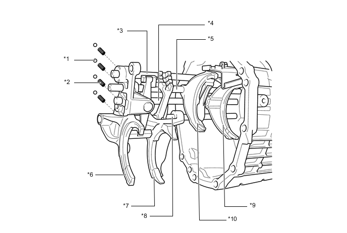
Text in Illustration *1 Shift Detent Ball *2 Compression Spring *3 No. 3 Shift Fork Shaft *4 No. 1 Shift Fork Shaft *5 No. 2 Shift Fork Shaft *6 No. 4 Shift Fork *7 No. 1 Shift Fork *8 No. 4 Shift Fork Shaft *9 No. 3 Shift Fork *10 No. 2 Shift Fork
-
-