CRUISE CONTROL SYSTEM
-
FUNCTION OF MAIN COMPONENTS
-
The main components in the cruise control system have the following functions:
Component Function Cruise Control Switch Main Switch Turns on/off the power to the cruise control system. CANCEL Switch A cancel signal can be output to the ECM through the operation of this switch. RES/+ Switch The acceleration function and resume control function can be performed by operating this switch. A signal is output to the ECM when this switch is operated. SET/- Switch The deceleration function and set control function can be performed by operating this switch. A signal is output to the ECM when this switch is operated. Speed Sensor Detects the vehicle speed and transmits a signal via the skid control ECU to the combination meter assembly. Throttle Body*1 Throttle Control Motor Adjusts the throttle valve to the limiter position in accordance with signals from the ECM. Throttle Position Sensor Transmits the throttle valve position information to the ECM. Injector*2 Adjusts the fuel injection volume based on the signals. Stop Light Switch Assembly Detects the depressing of the brake pedal and transmits a signal to the ECM. Clutch Switch Assembly*3 Detects the depressing of the clutch pedal and transmits a signal to the ECM. Park/Neutral Position Switch Assembly*4 Detects the shift position and transmits a signal to the ECM. Combination Meter Assembly Cruise Main Indicator Light
-
Illuminates when the cruise control switch has been pressed to turn the cruise control system on.
-
If the ECM detects a malfunction, this light illuminates in yellow to warn the driver*5 or this light turns off*6.
Cruise SET Indicator Light Illuminates when the SET/- switch on the cruise control switch has been pressed to set the cruise control system. Multi-information Display Displays a warning message to alert the driver in accordance with a signal provided by the ECM.*6 ECM
-
Controls the cruise control system in accordance with signals from the switches and sensors.
-
If the ECM detects a malfunction in the cruise control system, it will store a Diagnostic Trouble Code (DTC).
Injector Driver*7 Receives signals from the ECM to control the injector. TCM*8 Controls the automatic transmission in accordance with signals from the ECM. VSC OFF Switch Enables the driver to select "Normal Mode", "TRC OFF Mode", or "VSC OFF Mode".
-
*1: Models with gasoline engine
-
*2: Models with diesel engine
-
*3: Models with manual transmission
-
*4: Models with automatic transmission
-
*5: Models with analog display type combination meter assembly
-
*6: Models with Optitron display type combination meter assembly
-
*7: Models with 1KD-FTV engine
-
*8: Models with 1KD-FTV engine with automatic transmission
-
-
-
FUNCTION
-
The cruise control system has the following functions:
Function Outline Set Control When the main switch is turned on and the cruise control switch is pushed to the SET/- direction and released, the ECM stores the vehicle speed in the memory and continues to control the vehicle at that speed. The set speed is between 40 km/h (25 mph) and 200 km/h (125 mph). Coast Control Gasoline Engine When the cruise control switch is kept pushed to the SET/- direction while the cruise control system is running, the throttle control motor is energized in the throttle closing direction, and the vehicle keeps decelerating. The ECM stores the vehicle speed when the cruise control switch is released. From then on, the ECM controls the vehicle speed at that speed constantly. Diesel Engine When the cruise control switch is kept pushed to the SET/- direction while the cruise control system is running, the ECM decreases the fuel injection volume by regulating the 4 injectors. As the vehicle continues to decelerate, the ECM stores the vehicle speed at the time the cruise control switch is released. From then on, the ECM continues to control the vehicle at that speed. Tap-down Control When the difference between the actual vehicle speed and the set speed is less than 5 km/h (3 mph), the set speed can be lowered by approx. 1.6 km/h (1 mph) each time by operating the cruise control switch in the SET/- direction quickly within approx. 0.6 seconds. Accelerator Control Gasoline Engine When the cruise control switch is kept pushed to the RES/+ direction while the cruise control system is running, the throttle control motor is energized in the throttle opening direction. The vehicle keeps accelerating and the ECM stores the vehicle speed when the cruise control switch is released. From then on, the ECM controls the vehicle speed at that speed constantly. Diesel Engine When the cruise control switch is kept pushed to the RES/+ direction while the cruise control system is running, the ECM increases the fuel injection volume by regulating the 4 injectors. As the vehicle continues to accelerate, the ECM stores the vehicle speed at the time the cruise control switch is released. From then on, the ECM continues to control the vehicle at that speed constantly. Tap-up Control When the difference between the actual vehicle speed and the set speed is less than 5 km/h (3 mph), the set speed can be increased by approx. 1.6 km/h (1 mph) each time by operating the cruise control switch in the RES/+ direction quickly within approx. 0.6 seconds. Low Speed Limit Control The low speed limit is the lowest speed that the cruise control system can be set to and is set at approx. 40 km/h (25 mph). The cruise control system cannot be set below that speed. If the vehicle speed drops below that speed while running in the cruise control system, the cruise control system is canceled automatically. Resume Control After the cruise control system is canceled by a switch other than the main switch, the mode can be resumed and controlled at the set speed by operating the cruise control switch in the RES/+ direction when the vehicle speed returns above the low speed limit (approx. 40 km/h [25 mph]). Shift Down Control*1 When the vehicle is traveling uphill using cruise control, automatic transmission control may cause the transmission to shift down. During shift down control, when the end of uphill travel is determined, the transmission will shift up after a certain period of time. When the transmission shifts down during the accelerator control or the resume control, the transmission will shift up after the accelerator control or the resume control ends. Manual Cancel Control If any of the following signals is sent to the ECM while the cruise control system is running, the cruise control system is canceled accordingly.
-
Stop light switch on signal (depress the brake pedal)
-
Clutch switch assembly off signal (depress the clutch pedal)*2
-
Signal to move the shift lever from D or S to N*1
-
Signal to select the S1, S2 and S3 ranges*1
-
CANCEL switch on signal
-
Main switch off signal
Automatic Cancel Control When any of the following conditions occurs while the cruise control system is running, the set speed in the memory is cleared to cancel the cruise control system. Furthermore, the cruise main indicator light turns off*3 or illuminates in yellow*4 until the main switch is turned off, and the operation of the cruise control system is disabled until the main switch is turned on again.
-
The stop light switch has an open or short circuit.
-
The vehicle speed signal is abnormal.
-
The ETCS-i has a malfunction.*5
-
The ECD system has a malfunction.*6
When any of the following conditions occurs while the cruise control system is running, the set speed in the memory is cleared to cancel the cruise control system. Furthermore, the cruise main indicator light turns off*3 or illuminates in yellow*4 until the main switch is turned off, and the operation of the cruise control system is disabled until the ignition switch (engine switch*7) is turned off.
-
The stop light switch input signal is abnormal.
-
The cancel circuit has a malfunction.
When any of the following conditions occurs while the the cruise control system is running, the cruise control system is canceled. The cruise control system can be resumed at the set speed by operating the cruise control switch in the SET/- or RES/+ direction providing that the vehicle speed is above the low speed limit (approx. 40 km/h [25 mph]).
-
The vehicle speed falls below the low speed limit (approx. 40 km/h [25 mph]). The set speed in the memory is maintained.
-
The vehicle speed drops more than 16 km/h (10 mph) below the set speed. The set speed in the memory is cleared.
Other Control If any of the following conditions occur during cruise control driving, the cruise control is canceled. However, the set speed remains in the memory
-
- VSC is activated.
-
- TRC is activated for a period of time.*8
-
- The VSC or TRC system is turned off by pressing the VSC OFF switch.*8
-
- 4WD control ECU assembly requests to cancel the cruise control system.
When the engine switch is turned off, the set speed is not stored in the memory.
-
*1: Models with automatic transmission
-
*2: Models with manual transmission
-
*3: Models with Optitron display type combination meter assembly
-
*4: Models with analog display type combination meter assembly
-
*5: Models with gasoline engine
-
*6: Models with diesel engine
-
*7: Models with entry and start system
-
*8: Models with 1GD-FTV engine or 1GR-FE engine (models for Europe or Australia with automatic transmission), or models with 2TR-FE engine (destination package for Russia)
-
-
-
CONSTRUCTION
-
Cruise Control Switch
-
The cruise control switch consists of the main, RES/+, SET/- and CANCEL switches. The RES/+, SET/- and CANCEL switches are operated using a lever that operates in 3 directions.
-
The cruise control switch is an automatic reset (normally open) type that turns on only when the switch is being operated and turns off as soon as the driver releases the switch. Furthermore, the functions of the control switch are active only when the cruise control system has been turned on.
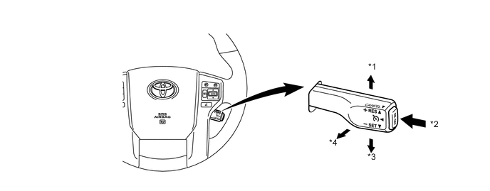
Text in Illustration *1 RES/+ *2 Main Switch *3 SET/- *4 CANCEL
-
-
Combination Meter Assembly
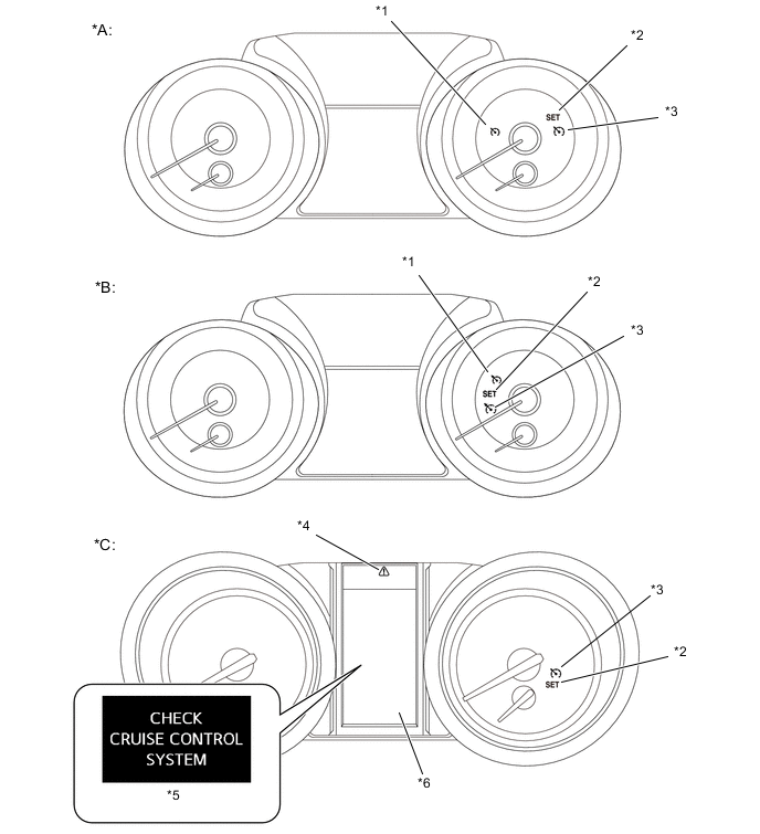
Text in Illustration *A Models with Analog Display Type Combination Meter Assembly with Segment Display Type Multi-information Display *B Models with Analog Display Type Combination Meter Assembly with Dot Display Type Multi-information Display *C Models with Optitron Display Type Combination Meter Assembly - - *1 Cruise Main Indicator Light (Yellow) *2 Cruise SET Indicator Light *3 Cruise Main Indicator Light (Green) *4 Master Warning Light *5 Warning Display *6 Multi-information Display
-
The combination meter assembly illuminates the indicator lights in accordance with each respective condition.
Condition 


Main Switch On Illuminates (Green) - - Set Control Illuminates (Green) Illuminates - Malfunction Occurred *1 Illuminates (Yellow) - - *2 - - Illuminates
-
*1: Models with analog display type combination meter assembly
-
*2: Models with Optitron display type combination meter assembly
-
-
-
-
DIAGNOSIS
-
If a malfunction occurs in the cruise control system, the ECM cancels the cruise control system. The ECM turns the cruise main indicator light in yellow*1 or turns off the cruise main indicator light*2 to inform the driver of a malfunction. Furthermore, the ECM displays a warning message on the multi-information display*2. At this time, the ECM memorizes the malfunction in the form of a 5-digit Diagnostic Trouble Code (DTC). For details of the DTC, refer to the Repair Manual.
-
*1: Models with analog display type combination meter assembly
-
*2: Models with Optitron display type combination meter assembly
-
-