EMISSION CONTROL SYSTEM
-
FUNCTION OF MAIN COMPONENTS
-
The main components of the emission control system are as follows:
Component Function ECM Controls the emission control system based on signals from each sensor. Electric EGR Control Valve Assembly Actuated by the ECM, this valve controls the flow rate of EGR gas. EGR Valve Position Sensor (Built into Electric EGR Control Valve Assembly) Detects the EGR valve position. Diesel Throttle Valve Actuated by the ECM, this valve controls the flow rate of intake air. No. 1 EGR Cooler Cools EGR gas. No. 2 EGR Valve Assembly Switches the flow passage of EGR gas in 2 stages. UREA Pump Control ECU* Controls the UREA SCR system based on signals from each sensor. Exhaust Gas Temperature Sensor Detects the exhaust gas temperature. No. 2 Exhaust Gas Temperature Sensor No. 3 Exhaust Gas Temperature Sensor No. 4 Exhaust Gas Temperature Sensor* Differential Pressure Sensor Monitors the differential pressure before and after the DPF to detect whether the DPF is clogged. Exhaust Fuel Addition Injector Assembly Injects fuel into the exhaust manifold according to signals from the ECM. Air Fuel Ratio Sensor Detects the oxygen concentration in exhaust gas. NOx Sensor (Nitrogen Oxides Sensor) Detects the concentration of NOx in the exhaust gas.
-
*: Models compliant with EURO 6 emission regulations
-
-
-
SYSTEM CONTROL
-
EGR System
-
This system is designed to help reduce and control NOx formation due to a reduction of peak temperature in the engine combustion chamber, which is accomplished by the introduction of an amount of inert gas into the intake manifold.
-
-
Catalyst Support Control
-
Determines the DPF catalyst conditions based on various signals, controls the injector assembly and exhaust fuel addition injector assembly, and controls the DPF catalyst conditions.
-
-
UREA SCR System (Models Compliant with EURO 6 Emission Regulation)
-
Urea solution is injected by the urea injector set to purify NOx in the exhaust gas.
-
-
-
FUNCTION
-
EGR System
-
The EGR system carries out the following controls:
-
The ECM actuates the electric EGR control valve assembly, which regulates the volume of EGR gas recirculation, in accordance with the engine condition.
-
The ECM switches the bypass passage of the No. 1 EGR cooler via the No. 2 EGR valve assembly in 2 stages in order to optimize the temperature of the EGR gas and clean exhaust gases.
-
-
-
Catalyst Support Control
-
If the DPF temperature is high under normal driving conditions, PM captured by the DPF is oxidized by the temperature of the DPF and is emitted as CO2 and H2O.
-
If the DPF temperature becomes low, catalyst performance decreases, resulting in an increase of the amount of PM stuck in the filter substrate. The ECM detects that the filter substrate is clogged by calculating the accumulated volume of the PM discharged by the engine. To reduce PM, the ECM controls the injection timing and the injection frequency of the injectors, and activates the exhaust fuel addition injector. At the same time, ECM controls the engine speed and glow plug assembly temperature via the glow plug controller. As a result, filter substrate temperature becomes high and PM reacts with active oxygen and changes into CO2 for purification. This is known as catalyst support control.
-
When PM has accumulated in the DPF while driving normally, the ECM automatically performs catalyst support control.
-
However, sufficient purification of the PM by the catalyst support control may not be possible when driving repeatedly over short distances. As a result, the PM accumulation limit may be surpassed. If a predetermined level of PM accumulation has been surpassed, the DPF indicator light in the combination meter is illuminated. This prompts the driver to drive at a constant speed (60 km/h or more) for automatic catalyst support control to be carried out.
-
In addition, if the driver keeps driving without driving at a constant speed (60 km/h or more), the DPF indicator light illuminates or blinks when a predetermined level of PM accumulation is surpassed. This prompts the driver to bring the vehicle to a dealer for manual catalyst support control to be carried out.
-
Moreover, if the driver keeps driving without bringing the vehicle to a dealer, PM accumulates further. In this situation, if the catalyst support control is conducted, the DPF could be destroyed. To prevent this, the MIL will be illuminated when a predetermined driving distance is reached. At the same time, the ECM changes the engine control to the fail-safe mode, thus controlling the amount of fuel injection to a minimum.
CAUTION:
During regeneration, observe the following precautions. Failure to do so may result in serious injury such as burns caused by the hot exhaust pipe and exhaust gases, or may cause a fire.
-
Do not place flammable materials near the exhaust pipe.
-
Make sure that there are no people near the exhaust pipe.
Tech Tips
-
When replacing the exhaust manifold converter sub-assembly with a new one, it is necessary to perform initialization of the DPF deteriorate data history in the ECM by using a Grobal TechStream (GTS).
-
When replacing the ECM with a new one, it is necessary to read DPF deteriorate data history from the installed ECM and then transfer that data history to the new ECM by using a Grobal TechStream (GTS). When the DPF deteriorate data history is not transferred, Diagnostic Trouble Code (DTC) is stored in the ECM, and the MIL comes on.
-
When replacing both the exhaust manifold converter sub-assembly and the ECM, it is necessary to perform initialization of the DPF deteriorate data history in the ECM using a Grobal TechStream (GTS). When DPF deteriorate history initialization is not performed, DTC is stored in the ECM and the MIL comes on.
-
-
-
UREA SCR System (Models Compliant with EURO 6 Emission Regulation)
-
A UREA SCR system is used to purify NOx in the exhaust gas. The urea SCR system injects urea solution into the exhaust gas to generate ammonia. The generated ammonia produces a chemical reaction with the NOx in the exhaust gas on the SCR catalyst, breaking it down into nitrogen and water, thereby purifying the exhaust gas.
-
The UREA SCR system is composed of a UREA pump control ECU, urea tank sub-assembly, urea injector set, urea pump, No.4 exhaust gas temperature sensor and NOx sensor (nitrogen oxides sensor).
-
In the UREA SCR system, the UREA pump control ECU controls the urea injector set and urea pump based on various signals.
-
-
-
CONSTRUCTION
-
Oxidation Catalyst
-
An oxidation catalyst is used to purify HC and CO in the exhaust gas.
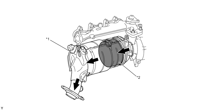
Text in Illustration *1 Exhaust Manifold Converter Sub-assembly *2 Oxidation Catalyst 
Exhaust Gas - -
-
-
DPF
-
A DPF catalyst is used to collect and purify PM.
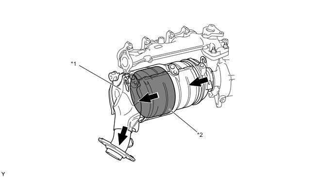
Text in Illustration *1 Exhaust Manifold Converter Sub-assembly *2 DPF Exhaust Gas - -
-
-
SCR Catalyst
-
2 SCR catalysts and an ammonia slip catalyst are provided in the front pipe area to improve NOx purification performance.
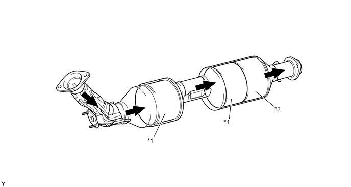
Text in Illustration *1 SCR Catalyst *2 Ammonia Slip Catalyst Exhaust Gas - -
-
-
UREA Pump
-
A urea pump is used, and is positioned in the bottom of the urea tank sub-assembly.
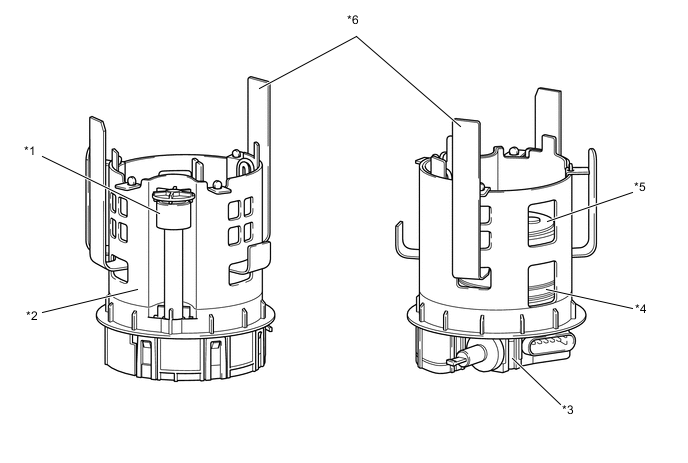
Text in Illustration *1 Float Sensor *2 Urea Solution Temperature Sensor *3 Pressure Sensor *4 Filter *5 Pump Motor *6 Heater -
The urea pump has the following functions:
Function Outline Pump Function While performing feedback control according to the pressure sensor inside the urea pump, the pump raises the pressure to approximately 500 kPa, sending urea solution to the urea injector set. Heating Function The heater inside the urea pump is operated to thaw the urea solution so that exhaust gas can be purified even when the ambient temperature is low and the urea solution freezes. The heater turns on and off according to the urea solution temperature sensor inside the urea pump. Filter Function Foreign matter that enters the urea tank sub-assembly is collected by the filter inside the urea pump, preventing foreign matter from getting jammed in the urea pump and urea injector set. Level Gauge Function The fluid level position is detected by the float sensor inside the urea pump in order to detect the remaining quantity of urea solution inside the urea tank sub-assembly.
-
-
EGR Valve
-
A DC motor type electric EGR control valve assembly is used. The placement of the electric EGR control valve assembly at the intersection between the intake passage and EGR bypass facilitates the uniform distribution of EGR gas and intake air.
-
An EGR valve position sensor is provided in the electric EGR control valve assembly. This sensor enables EGR valve control at a higher level of precision by detecting the opening angle of the EGR valve.
Text in Illustration *1 Electric EGR Control Valve Assembly - -
-
-
EGR Pipe and EGR Valve
-
A water-cooled type No. 1 EGR cooler is used between the exhaust manifold and electric EGR control valve assembly. In the water-cooled type No. 1 EGR cooler, engine coolant flows through eightlayered gas passage to cool down the EGR gas.
-
The No. 2 EGR valve assembly is used. The EGR gas passage is switched in 2 stages by the No. 2 EGR valve assembly to optimize the temperature of the EGR gas.
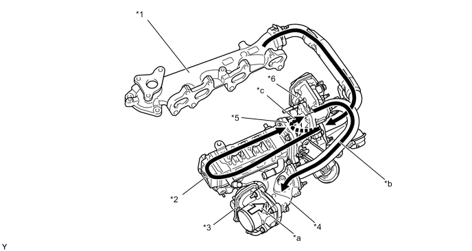
Text in Illustration *1 Exhaust Manifold *2 No. 1 EGR Cooler *3 Diesel Throttle Body Assembly *4 Intake Manifold *5 No. 2 EGR Valve Assembly *6 Electric EGR Control Valve Assembly *a Intake Air *b EGR Gas *c EGR Gas (through Bypass Passage) - -
-
-
Exhaust Fuel Addition Injector
-
The exhaust fuel addition injector assembly is installed on the exhaust manifold. Fuel is supplied by the injector to maintain the temperature of the catalyst, removing PM.
-
An exhaust fuel addition injector assembly consists of a needle valve body, a needle valve, and a solenoid valve.

Text in Illustration *1 Solenoid Valve *2 Needle Valve *3 Needle Valve Body - -
-
-
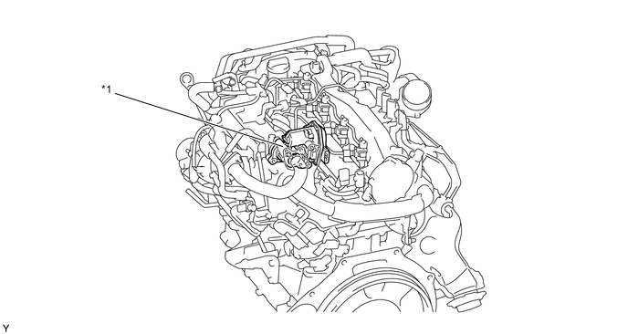
Differential Pressure Sensor
-
The differential pressure sensor measures the pressure differences between before and after the DPF with PM in order to detect clogging.
-
The sensor is mounted on the cylinder head. The DPF and the sensor are connected with pipes and hoses.
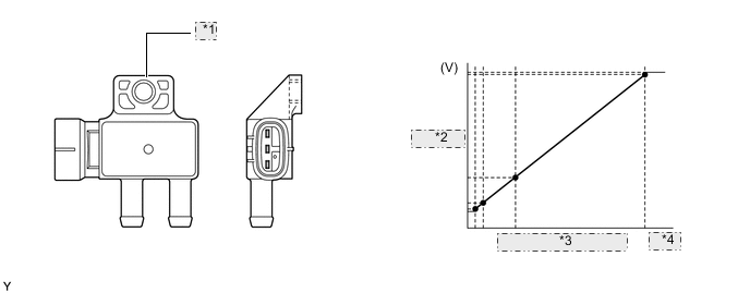
*1 Differential Pressure Sensor *2 Output Voltage *3 Differential Pressure *4 (kPa)
-
-
Exhaust Gas Temperature Sensor
-
An exhaust gas temperature sensor, which is a thermistor type, is installed before the oxidation catalyst, before the DPF, after the DPF and after the SCR catalyst*, in order to detect the temperature of the exhaust gas.
-
*: Models compiant with EURO 6 emission regulation

Text in Illustration *1 Exhaust Gas Temperature Sensor - - -
-
-
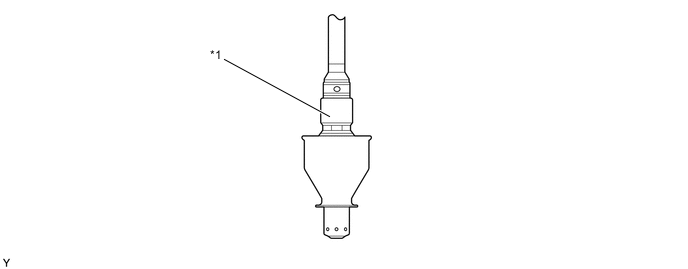
Air Fuel Ratio Sensor
-
An air fuel ratio sensor is used to optimize the combustion and the catalyst conditions. The structure of the sensor is layered to promote early activation, achieving air fuel ratio feedback control in the early stages of engine start.
-
The air fuel ratio sensor is installed after the DPF catalyst.
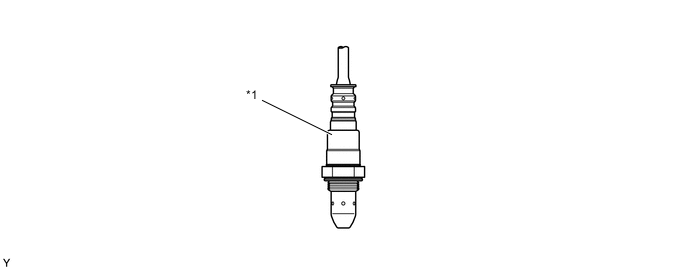
Text in Illustration *1 Air Fuel Ratio Sensor - -
-
-
NOx Sensor
-
An NOx sensor (nitrogen oxides sensor) is installed in center exhaust pipe assembly, in order to detects the concentration of NOx in the exhaust gas.
Text in Illustration *1 NOx Sensor (Nitrogen Oxides Sensor) - -
-
-