FUEL SYSTEM
-
SYSTEM CONTROL
-
Common-rail System
-
In this system, the highly pressurized fuel supplied by the supply pump is stored in the common-rail, and the ECM controls the injection timing and injection volume of the injectors.
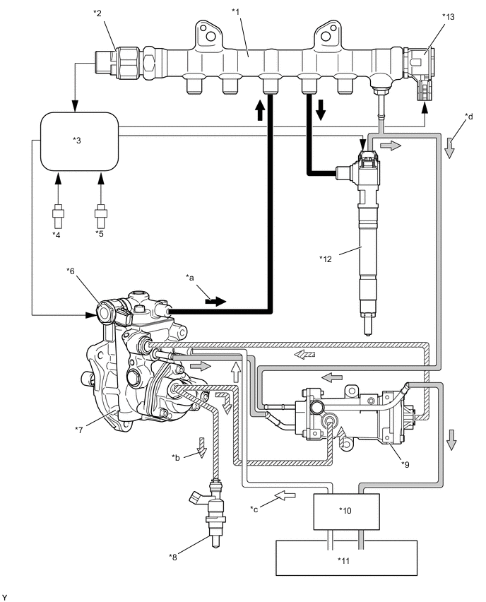
Text in Illustration *1 Common-rail Assembly *2 Fuel Pressure Sensor *3 ECM *4 Crank Position Sensor *5 Cam Position Sensor *6 Pre-stroke Control Valve *7 Injection or Supply Pump Assembly *8 Exhaust Fuel Addition Injector Assembly *9 Pressurised Fuel Filter *10 Fuel Filter Assembly *11 Fuel Tank Assembly *12 Injector Assembly *13 Pressure Discharge Valve - - *a Fuel (High Pressure) *b Fuel (Feed Pressure) *c Fuel (Suction) *d Fuel (Return)
-
-
-
CONSTRUCTION
-
Supply Pump
-
An HP5S type injection or supply pump assembly is used.
-
The injection or supply pump assembly consists of a camshaft, a plunger, a check valve a pre-stroke control valve and a feed pump.
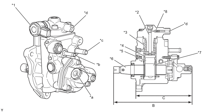
Text in Illustration *1 Pre-stroke Control Valve *2 Plunger *3 Spring *4 Shoe *5 Roller *6 Camshaft *7 Double Cam *8 Check Ball *a To Exhaust Fuel Addition Injector and Pressurised Fuel Filter *b Fuel Return Port (To Pressurised Fuel Filter) *c Fuel Inlet Port (From Fuel Tank) *d To Common-rail Assembly Supply Pump Specifications Type HP5S Length B 202.2 mm (7.96 in.) C 144.6 mm (5.69 in.) Pre-stroke Control Valve 1 Plunger φ 6.5 mm x 1 Weight 3970 g (8.75 lb)
-
-
Common-rail
-
The function of the common-rail assembly is to store the fuel that has been pressurized by the injection or supply pump assembly.
-
The common-rail assembly is provided with a fuel pressure sensor and pressure discharge valve.
-
The fuel pressure sensor detects the fuel pressure in the common-rail assembly.
-
The pressure discharge valve regulates the fuel pressure. In the pressure discharge valve, the plunger opens and closes in accordance with the actuation signals from the ECM. Thus, it regulates pressure by releasing excess pressure from the common-rail assembly. In addition, it has a pressure reduction function in case of emergency.
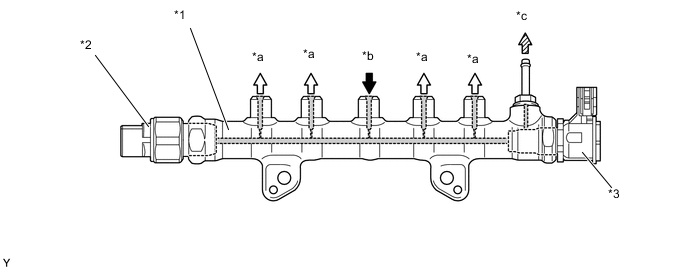
Text in Illustration *1 Common-rail Assembly *2 Fuel Pressure Sensor *3 Pressure Discharge Valve - - *a To Injector Assembly *b From Injection or Supply Pump Assembly *c To Fuel Tank Assembly (Excess Pressure) - -
-
-
Injector
-
Each injector assembly consists of a nozzle needle, a control plate and a solenoid valve.
-
An injector compensation value and a Quick Response (QR) code containing encoded characteristics of the injector are printed on each injector.
-
The injector compensation value and QR code contain various pieces of information regarding the injector, such as model code and injection volume correction.
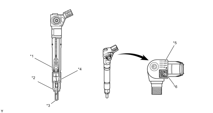
Text in Illustration *1 Solenoid *2 Nozzle Needle *3 Low Suck Volume Nozzle *4 Control Plate *5 Injector Compensation Value *6 QR Code
-
-
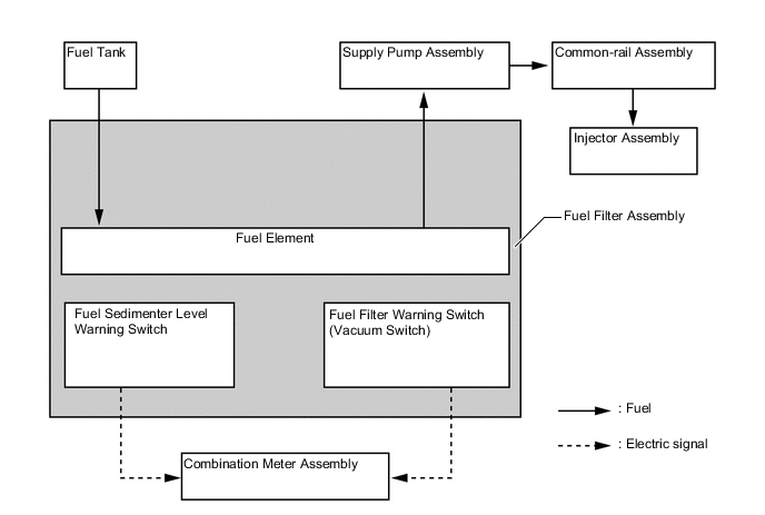
Fuel Filter
-
A cartridge type fuel filter assembly is used.
-
A paper filter element that offers high filtering efficiency and captures the particles is used.
-
A fuel filter warning switch is provided in the fuel filter assembly.
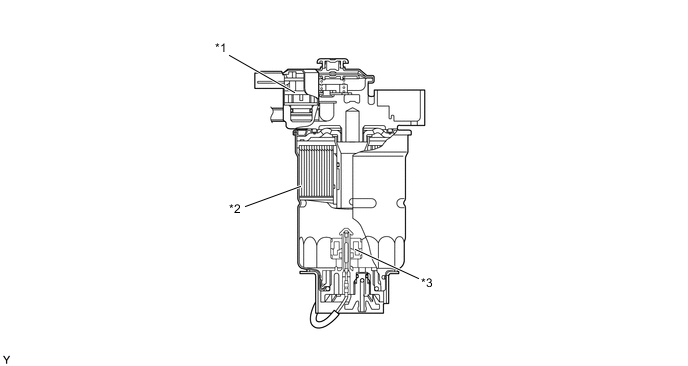
Text in Illustration *1 Fuel Filter Warning Switch (Vacuum Switch) *2 Fuel Filter Element *3 Fuel Sedimenter Level Warning Switch - -
-
-
Fuel Tank
-
A dual fuel tank is used.*
-
*: Models with dual fuel tank
-
-
-
-
OPERATION
-
Supply Pump
-
When the cam rotates the roller is pushed up, and in turn the plunger is pushed upward as well. When the plunger is not pushed up by the cam, it is pushed back down by the spring.
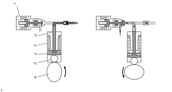
Text in Illustration *1 Pre-stroke Control Valve *2 Plunger *3 Spring *4 Shoe *5 Roller *6 Double Cam -
The ECM controls the closing timing of the pre-stroke control valve while the plunger is moving up in order to adjust the fuel supply volume. As a result, the fuel pressure in the common rail assembly is controlled to the target injection pressure.
-
When the pre-stroke control valve is closed while the plunger is moving up, the fuel pressure increases. When the fuel pressure exceeds the common-rail pressure, fuel is supplied to the common rail assembly.
-
When the closing timing of the pre-stroke control valve is delayed, the length of pressure-fed strokes will decrease, as well as the fuel discharge volume.
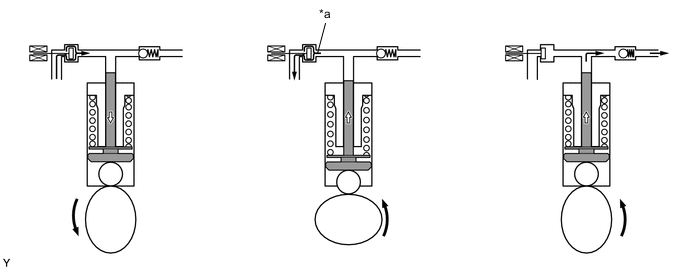
Text in Illustration *a Return Fuel - - -
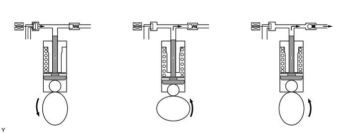
When the closing timing of the pre-stroke control valve is hastened, the length of pressure-fed strokes will increase, as well as the fuel discharge volume.
-
When the pre-stroke control valve is closed while the plunger is moving up, the fuel pressure increases. When the fuel pressure exceeds the common-rail pressure, fuel is supplied to the common rail assembly.
-
-
Injector
-
Current flows through the solenoid coil and the valve is pulled up.
-
Fuel flows out from the orifice (out) in the control chamber.
-
The fuel pressure in the control chamber drops.
-
The nozzle needle moves up due to the differential pressure above and below the nozzle needle.
-
Fuel is injected through the nozzle.
-
Current through the solenoid coil is stopped and the control valve is closed.
-
Fuel flows into the control chamber through the orifice (in) and the control plate moves down.
-
The pressure in the control chamber increases causing the force acting above and below the nozzle needle to reverse due to the fuel pressure.
-
The nozzle needle moves down and closes to stop injection.
-
When the control chamber pressure equalize, the control plate rises due to the force of the spring.
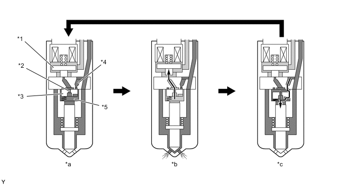
Text in Illustration *1 Control Valve *2 Out-orifice *3 Control Plate *4 In-orifice *5 Control Chamber - - *a Before fuel injection *b Fuel injection *c After fuel injection - - 
High Fuel Pressure 
Low Fuel Pressure
-
-
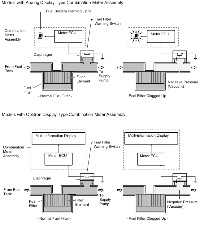
Fuel Filter
-
When the water in the sedimenter section reaches a certain amount, the fuel sedimenter level warning switch comes on, the warning light in the combination meter assembly blinks the multi buzzer sounds.*1
-
When the water in the sedimenter section reaches a certain amount, the fuel sedimenter level warning switch comes on, the multi-information display in the combination meter assembly displays, the master warning light in the combination meter assembly illuminates and the multi buzzer sounds. For details, see the METER / GAUGE / DISPLAY section.*2
-
A fuel filter warning switch, which turns on or off when the internal vacuum of the filter increases, is provided in the fuel filter. This switch, which turns off when the internal vacuum of the fuel filter increases to a predetermined level, is connected by wire to the combination meter assembly.
-
When the combination meter assembly detects that the internal vacuum of the fuel filter has increased (by way of the fuel filter warning switch off signal), it determines that the fuel filter has become clogged. Then, it illuminates the fuel system warning light on the combination meter assembly to urge the driver to replace the fuel filter.*1
-
When the combination meter assembly detects that the internal vacuum of the fuel filter has increased (by way of the fuel filter warning switch off signal), it determines that the fuel filter has become clogged. Then, it displays the multi-information display on the combination meter assembly to urge the driver to replace the fuel filter. For details, see the METER / GAUGE / DISPLAY section.*2
-
*1: Models with analog display type combination meter assembly
-
*2: Models with Optitron display type combination meter assembly
-
-
-
Fuel Tank
-
On the models with dual fuel tank, a fuel pump and jet pump are provided in the main fuel tank to transfer the fuel from sub fuel tank to main fuel tank. This is accomplished by utilizing the fuel flow through the jet pump. The pressure difference is created by the fuel as it passes through the venturi, and it is used to suck the fuel out of the sub fuel tank and send it to the main fuel tank.
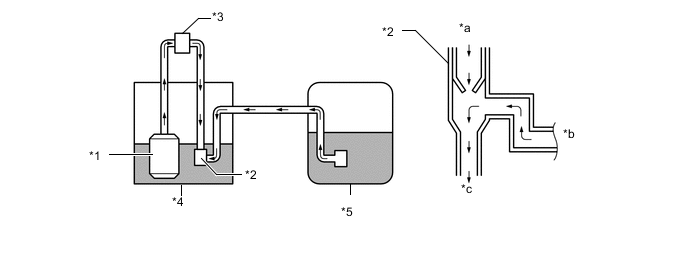
Text in Illustration *1 Fuel Pump Assembly *2 Jet Pump *3 Fuel Pump Filter Assembly *4 Main Fuel Tank *5 Sub Fuel Tank - - *a From Fuel Pump *b From Sub Fuel Tank *c To Main Fuel Tank - -
-
-