INTAKE SYSTEM
-
CONSTRUCTION
-
Diesel Throttle Body
-
A diesel throttle valve with a DC motor type throttle control motor is used to reduce exhaust gas emissions, as well as improve diesel throttle valve responsiveness and fuel economy.
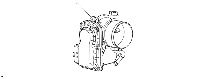
Text in Illustration *1 Diesel Throttle Body Assembly - -
-
-
Intake Manifold
-
The intake location for EGR gas is optimized to control differences in EGR gas volume between cylinders, improving fuel economy and reducing noise and vibration.
-
A vacuum-actuated swirl control valve is provided in one of the 2 intake ports provided for each cylinder. The swirl control valve consists of a stainless steel shaft and an actuator, which are integrated in the valve. The swirl control valve with 2-stage control is used.
-
A curved surface is used for the intake manifold to reduce noise from the engine.
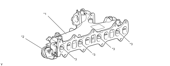
Text in Illustration *1 Intake Manifold *2 Actuator *3 Swirl Control Valve - -
-
-
Intercooler
-
An air-cooled intercooler assembly is used in order to lower the intake air temperature, improve engine performance and achieve cleaner exhaust gas emissions. It is located in front of the radiator assembly.
-
The intercooler assembly is made of aluminum.
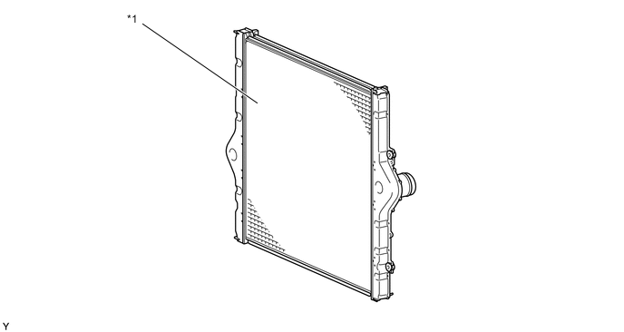
Text in Illustration *1 Intercooler Assembly - -
-
-
Turbocharger
-
A variable nozzle vane type turbocharger sub-assembly is used. A water jacket is provided in the bearing housing to improve the cooling performance of the turbocharger sub-assembly.
-
The shape of the turbine wheel is optimized for downsizing, improving higher rotational speed, and dynamic response and transitioning performance, as well as reducing fuel consumption and exhaust gas emissions. Also, a full-back disk is used for the turbine wheel to improve reliability of the turbine wheel and allow exhaust gas to flow smoothly to the turbine wheel, improving turbo efficiency and reducing fuel consumption.
-
This turbocharger sub-assembly has achieved great improvements in low-speed torque, maximum output, fuel consumption and emission reduction. These improvements have been accomplished through variable control of the nozzle vane position, and an optimal velocity of the exhaust gas inflow to the turbine at all times in response to the engine condition.
-
The variable nozzle vane type turbocharger sub-assembly consists primarily of a compressor wheel, turbine wheel, nozzle vane, unison ring, drive arm, driven arm, actuator (motor and nozzle vane position sensor) and nozzle vane control link.
-
The ECM outputs a signal to the turbocharger sub-assembly, which operates the actuator, to control the nozzle vane position.
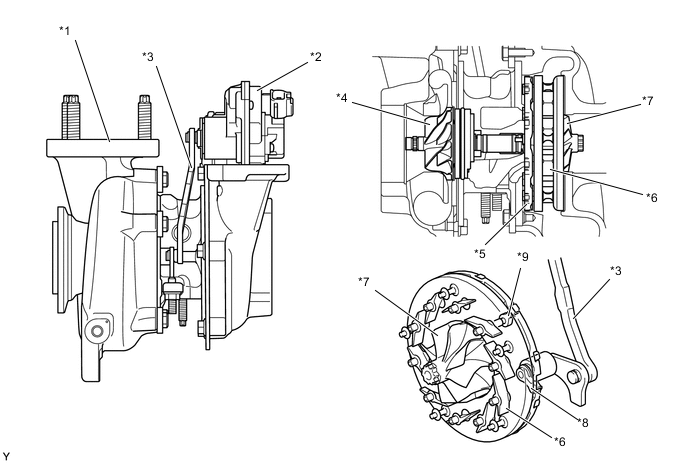
Text in Illustration *1 Turbocharger Sub-assembly *2 Actuator *3 Linkage *4 Compressor Wheel *5 Unison Ring *6 Nozzle Vane *7 Turbine Wheel *8 Drive Arm *9 Driven Arm - -
-
-
-
OPERATION
-
Turbocharger
-
The exhaust gas from the exhaust manifold goes through the nozzle vane inside the turbocharger housing and flows to the exhaust pipe through the turbine. The speed of the turbine (supercharging pressure) differs depending on the flow velocity of the exhaust gas going through the turbine, and the flow velocity of the exhaust gas is controlled by the opening. When there is less exhaust gas, such as during idling, the nozzle vane is almost fully closed, but as there is a slight clearance between the vanes, the exhaust gas flows through this clearance to the exhaust pipe. Therefore, there is no bypass.

Text in Illustration *1 Nozzle Vane - - 
Intake Air 
Exhaust Gas -
At Low Load Range or Low Speed Range
-
The actuator moves the linkage in the closing direction of the nozzle vanes in accordance with signals from the ECM.
-
This results in increasing the velocity of the exhaust gas flowing to the turbine, as well as the speed of the turbine. As a result, torque is improved when the engine is running at low speeds.
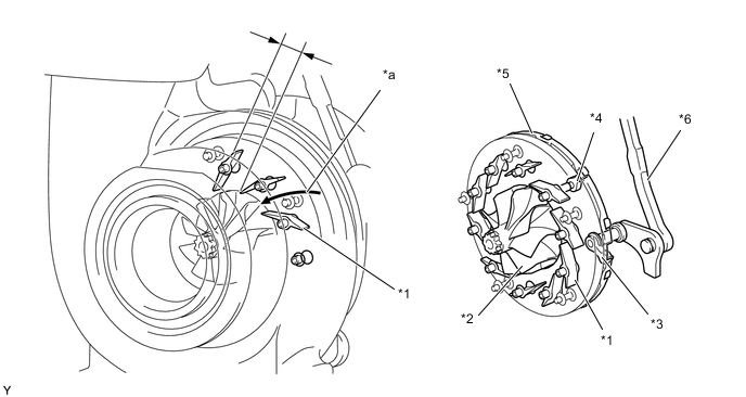
Text in Illustration *1 Nozzle Vane *2 Turbine Wheel *3 Drive Arm *4 Driven Arm *5 Unison Ring *6 Linkage *a Exhaust Gas Flow - -
-
-
At High Load Range or Medium-to-high Speed Range
-
The actuator moves the linkage in the opening direction of the nozzle vanes in accordance with signals from the ECM. This opens the nozzle vane and holds the specified supercharging pressure, lowering the back pressure and improving the output and fuel consumption.
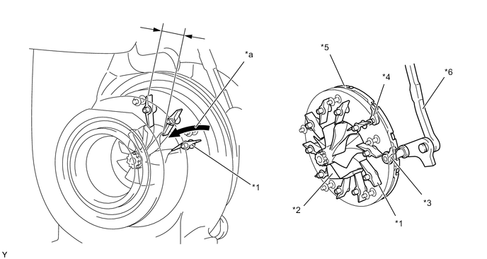
Text in Illustration *1 Nozzle Vane *2 Turbine Wheel *3 Drive Arm *4 Driven Arm *5 Unison Ring *6 Linkage *a Exhaust Gas Flow - -
-
-
-