ENGINE UNIT
-
CONSTRUCTION
-
Cylinder Head Cover
-
The cylinder head cover sub-assembly is made of plastic to reduce weight and noise.
-
An oil delivery pipe is provided on the inside of the cylinder head cover sub-assembly.
-
An oil mist separator is used in the cylinder head cover sub-assembly to reduce oil consumption.
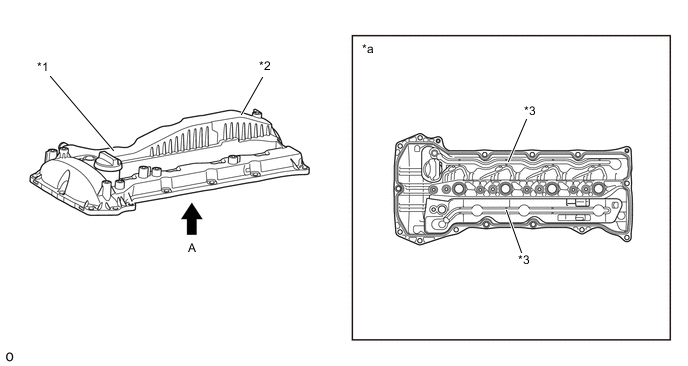
Text in Illustration *1 Cylinder Head Cover Sub-assembly *2 Oil Mist Separator *3 Oil Delivery Pipe - - *a View from A - -
-
-
Cylinder Head Gasket
-
A cylinder head gasket with a grommet and 2-layer bead structure is used to improve sealing performance.
-
The surface is coated in fluorine rubber to improve sealing performance.
-
The size of the water holes is optimized for optimal coolant flow volume to each area.
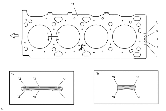
Text in Illustration *1 Cylinder Head Gasket Sub-assembly *2 Full-bead *3 Half-bead - - *a F - F Cross Section *b G - G Cross Section 
Front - - Tech Tips
There are 5 sizes of new cylinder head gaskets indicated by the number of holes labeled "A", "B", "C", "D" and "E" in accordance with the piston protrusion. For details, refer to the Repair Manual.
-
-
Cylinder Head
-
The cylinder head sub-assembly is made of aluminum alloy.
-
The injector assembly is located in the center of the combustion chamber in order to improve engine performance and to achieve clean emissions.
-
A tangential port and a helical port are used. These intake ports are used for stimulating combustion by producing strong swirling airflow and high flow volume.
-
The position and shape of the 2 intake ports are optimized to improve engine performance and fuel economy, as well as produce clean emissions.
-
A vertical 2-stage construction is used for the water jacket. By having coolant flow and collect in the water jacket on the lower side, combustion chamber cooling and capacity are both optimized to achieve early engine warm-up and improve reliability and fuel economy.
-
A glow plug assembly is placed between the intake ports of each cylinder to ensure startability.

Text in Illustration *1 Cylinder Head Sub-assembly *2 Water Jacket *3 Tangential Port *4 Helical Port *a A- A Cross Section *b B - B Cross Section
-
-
Cylinder Block
-
The cylinder block sub-assembly is constructed of liner-less cast iron alloy.
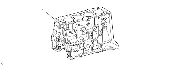
Text in Illustration *1 Cylinder Block Sub-assembly - -
-
-
Piston
-
A piston provided with a combustion chamber is used.
-
The piston is made of aluminum alloy.
-
A cooling channel has been provided to reduce the piston temperature, and achieve high reliability.
-
The shape of the piston skirt portion is optimized to achieve fuel economy and to achieve reliability.
-
Resin coating is provided to the piston skirt portion, reducing friction to improve fuel economy.
-
The shape of the piston ring is optimized to improve fuel economy.

Text in Illustration *1 Piston *2 Cooling Channel *3 Ni-resist Cast Iron Ring Carrier *4 No. 1 Compression Ring *5 No. 2 Compression Ring *6 Oil Ring *a Resin Coating *b PVD Coating
-
-
Connecting Rod and Connecting Rod Bearing
-
The connecting rod sub-assemblies are made of high tension material, and their shape is optimized to achieve weight reduction, reliability, improving quietness and reducing friction.
-
The upper side of the connecting rod bearing has an attached overlay to ensure reliability against high internal cylinder pressure and to reduce friction.
-
The connecting rod sub-assembly and connecting rod bearing both use lead-free materials, in consideration of environmental problems.
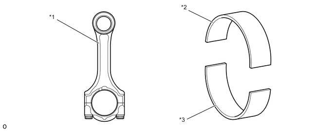
Text in Illustration *1 Connecting Rod Sub-assembly *2 No. 1 Connecting Rod Bearing *3 No. 2 Connecting Rod Bearing - -
-
-
Crankshaft and Bearing
-
The shape of the crankshaft is optimized to achieve weight reduction, reliability and quietness.
-
The lining surface of the crankshaft bearing is given micro-groove processing to ensure proper initial fit and long-term reliability.
-
A crankshaft bearing with an attached overlay is used on models with a stop and start system to ensure reliability for frequent engine starting and stopping.
-
The crankshaft and crankshaft bearing both use lead-free materials, in consideration of environmental problems.
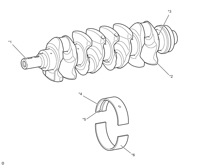
Text in Illustration *1 Crankshaft *2 Balance Weight *3 Oil Hole *4 No. 1 Crankshaft Bearing *5 Oil Groove *6 No. 2 Crankshaft Bearing
-
-
Valve Mechanism
-
This engine uses valve rocker arm sub-assemblies with built-in needle roller bearings. This reduces the friction that occurs between the cams and the roller rocker arms when the valves are pushed down, thus improving fuel economy.
-
A valve lash adjuster assembly, which maintains a constant zero valve clearance through the use of oil pressure and spring force, is used.
-
Oil lubrication for the valve rocker arm sub-assemblies are conducted by the oil delivery pipe in the cylinder head cover.
-
The intake camshaft and exhaust camshaft are driven by the crankshaft via the timing chain.

Text in Illustration *1 Timing Chain Guide *2 Camshaft Timing Sprocket *3 No. 2 Chain Tensioner Assembly *4 No. 2 Chain Tensioner Slipper1 *5 No. 1 Chain Tensioner Slipper *6 No. 1 Chain Tensioner Assembly *7 No. 1 Chain Vibration Damper *8 Chain Sub-assembly *9 No. 2 Chain Vibration Damper *10 No. 2 Chain Sub-assembly *11 Exhaust Valve *12 Intake Valve *13 Intake Camshaft *14 Exhaust Camshaft *15 No. 1 Valve Rocker Arm Sub-assembly *16 Valve Lash Adjuster Assembly
-
-
Valve Lash Adjuster
-
The valve lash adjuster assembly, which is located at the fulcrum of the No. 1 valve rocker arm subassembly, consists primarily of a plunger, plunger spring, check ball and check ball spring.
-
The engine oil supplied by the cylinder head and the built-in spring actuates the valve lash adjuster assembly. The oil pressure and the spring force that act on the plunger push the No. 1 valve rocker arm sub-assembly against the cam, in order to adjust the valve clearance that is created during the opening and closing of the valve. As a result, engine noise has been reduced.

Text in Illustration *1 Exhaust Camshaft *2 No. 1 Valve Rocker Arm Sub-assembly *3 Valve Lash Adjuster Assembly *4 Oil Passage *5 Intake Camshaft *6 Check Ball *7 Check Ball Spring *8 Plunger *9 Plunger Spring - -
-
-
Camshaft
-
The cam nose has been chill-treated to increase its abrasion resistance.
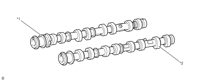
Text in Illustration *1 Exhaust Camshaft *2 Intake Camshaft
-
-
Balance Shaft
-
The balance shaft and housing are integrated to improve serviceability.
-
The balance shaft operates using the chain and gears, reducing noise.
-
A low-friction chain is used, reducing friction. Also, optimal tension is provided to improve quietness and to achieve reliability.
-
The balancer assembly is installed to the cylinder block assembly to reduce vibration and noise.

Text in Illustration *1 No. 3 Chain Sub-assembly *2 Balance Shaft Gear Sub-assembly *3 No. 2 Balance Shaft Housing *4 No. 1 Balance Shaft Sub-assembly *5 No. 1 Balance Shaft Housing *6 No. 2 Balance Shaft Sub-assembly
-
-
Timing Chain and Chain Tensioner
-
The chain sub-assembly uses a 9.525 mm (0.375 in.) pitch high-strength roller chain, and the No. 2 chain sub-assembly and No. 3 chain sub-assembly uses a 8.000 mm (0.315 in.) pitch high-strength roller chain, reducing friction.
-
Resin is used for the chain slipper and chain damper, reducing friction and increasing abrasion resistance.
-
A timing chain guide is provided between the intake camshaft and exhaust camshaft to suppress vibrations in the chain sub-assembly and improve quietness and to achieve reliability. Also, resin is used for the sliding portion of the chain, in consideration of abrasion resistance.
-
The chain tensioner uses the spring and oil pressure to always maintain appropriate tension in the chain subassembly and No. 2 chain sub-assembly, ensuring quietness and reliability. Also, the chain tensioner uses an internal oil retention mechanism and a ratchet mechanism to improve quietness when starting the engine and low engine rotation.
-
A chain tensioner gasket is used to improve oil retention, improving quietness when starting the engine.
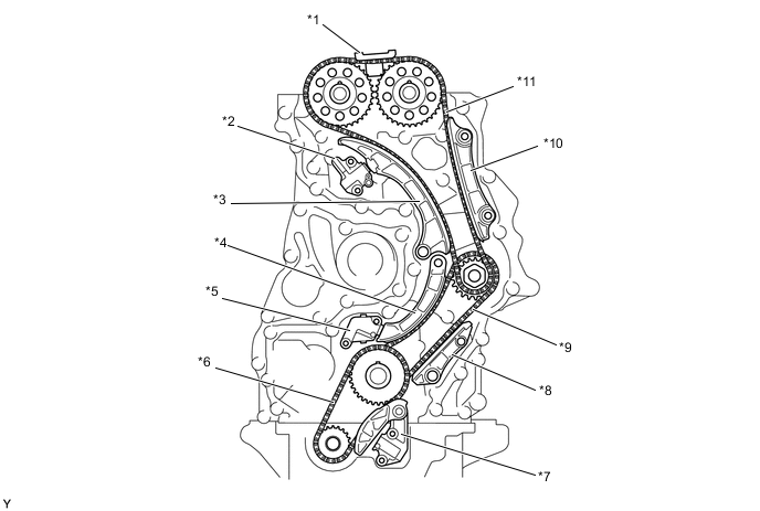
Text in Illustration *1 Timing Chain Guide *2 No. 2 Timing Chain Tensioner *3 No. 2 Chain Tensioner Slipper *4 No. 1 Chain Tensioner Slipper *5 No. 1 Timing Chain Tensioner *6 No. 3 Chain Sub-assembly *7 No. 3 Timing Chain Tensioner *8 No. 1 Chain Vibration Damper *9 Chain Sub-assembly *10 No. 2 Chain Vibration Damper *11 No. 2 Chain Sub-assembly - -
-
-
V-ribbed Belt
-
Accessory components are driven by a serpentine belt consisting of a single V-ribbed belt. It reduces the overall engine length, weight and number of engine parts.
-
An automatic tensioner eliminates the need for tension adjustment.
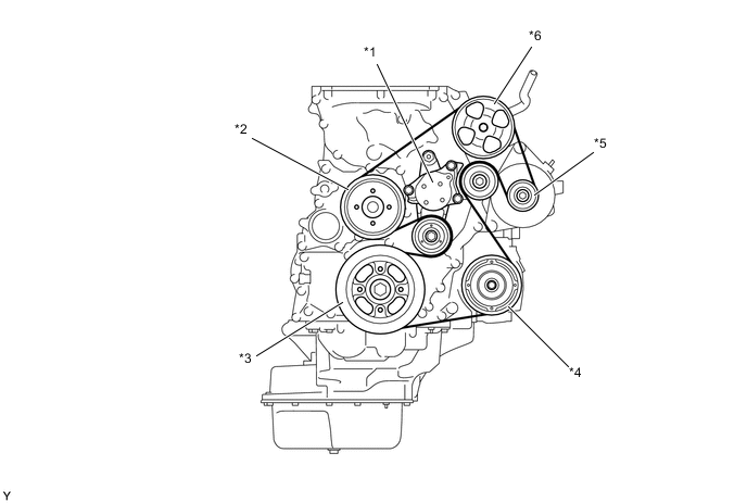
Text in Illustration *1 V-ribbed Belt Tensioner Assembly *2 Water Pump Pulley *3 Crankshaft Pulley *4 Compressor Pulley *5 Alternator Pulley *6 Power Steering Pump Pulley
-
-