ENGINE UNIT
-
CONSTRUCTION
-
Cylinder Head Cover
-
The cylinder head cover is made of plastic to reduce weight and noise.
-
A baffle plate is provided on the inside of the cylinder head cover to reduce the consumption of engine oil through blow-by gas.
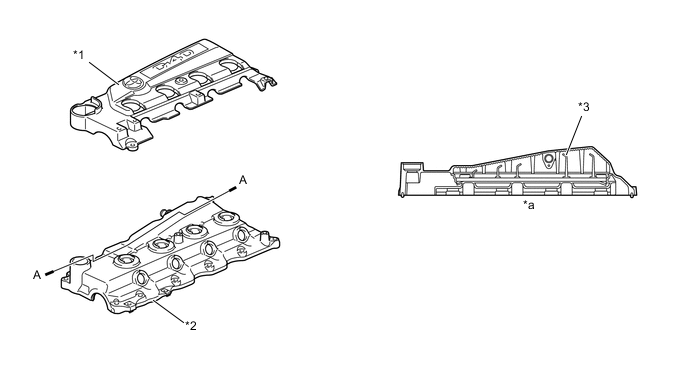
Text in Illustration *1 No. 2 Cylinder Head Cover *2 Cylinder Head Cover *3 Baffle Plate - - *a A - A Cross Section - -
-
-
Cylinder Head Gasket
-
A steel-laminate type cylinder head gasket is used.
-
A shim has been provided around the cylinder bore to increase the sealing surface, thus achieving excellent sealing performance.
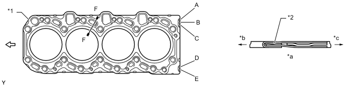
Text in Illustration *1 Cylinder Head Gasket *2 Shim *a F - F Cross Section *b Cylinder Bore Side *c Outer Side - - 
Front - - Tech Tips
There are 5 sizes of new cylinder head gaskets, marked "A", "B", "C", "D", or "E" in accordance with piston protrusion. For details, refer to the Repair Manual.
-
-
Cylinder Head
-
The cylinder head is made of aluminum alloy. The injector has been located in the center of the combustion chamber in order to improve engine performance and to achieve cleaner emissions.
-
Two intake ports with different shapes have been combined to promote the mixture of fuel and air by optimizing the swirl in the cylinder.
-
A vertical 2-stage construction is used for the water jacket to improve cooling performance.
-
A glow plug is placed between the intake ports of each cylinder to ensure startability.
-
The passage for the EGR is provided in the cylinder head. By cooling the exhaust gas, it is possible to recirculate a large amount of exhaust gas.
-
On the models without EGR control, an EGR hole cover plate which plugs the EGR passage is provided.
-
The cylinder head bolt employs plastic region tightening bolts.
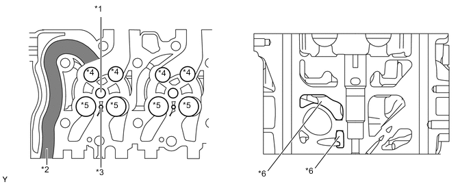
Text in Illustration *1 Injector Hole *2 EGR Passage *3 Glow Plug Hole *4 Exhaust Valve Hole *5 Intake Valve Hole *6 Water Jacket
-
-
Cylinder Block
-
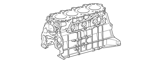
The cylinder block is constructed of liner-less cast iron alloy.
-
-
Piston
-
A piston provided with a combustion chamber is used.
-
The piston is made of aluminum alloy.
-
A cooling channel has been provided to reduce the piston temperature, and achieve high reliability.
-
The top ring groove uses a Ni-resist cast iron ring carrier to improve wear resistance.
-
A Physical Vapor Deposition (PVD) coating has been applied to the surface of the No. 1 compression ring, in order to improve its wear resistance.
-
Except on the models compliant with EURO 4 emission regulations, a chromium plating coating has been applied to the surface of the No. 2 compression ring, in order to improve its wear resistance.
-
Except on the models compliant with EURO 4 emission regulations, a PVD coating has been applied to the surface of the oil ring.
-
A resin coating is applied to the piston skirt portion, to achieve reduction of friction loss.
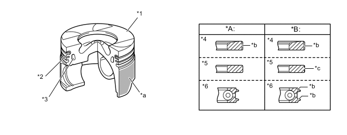
Text in Illustration *A Models Compliant with EURO 4 Emission Regulations *B Except Models Compliant with EURO 4 Emission Regulations *1 Piston *2 Ni-resist Cast Iron Ring Carrier *3 Cooling Channel *4 No. 1 Compression Ring *5 No. 2 Compression Ring *6 Oil Ring *a Resin Coating *b PVD Coating *c Chromium Plating - -
-
-
Connecting Rod Sub-assembly and Connecting Rod Bearing
-
The connecting rods are made of high-strength material to ensure the proper strength.
-
Knock pins are used at the mating surfaces of the bearing caps of the connecting rod to minimize the shifting of the bearing caps during assembly.
-
Plastic region tightening bolts are used.
-
An aluminum bearing is used for the connecting rod bearings.
-
The lining surface of the connecting rod bearing has been micro-grooved to achieve an optimal amount of oil clearance. As a result, cold-engine cranking performance has been improved and engine vibrations have been reduced.
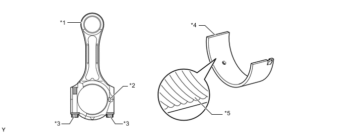
Text in Illustration *1 Connecting Rod Sub-assembly *2 Knock Pin *3 Plastic Region Tightening Bolt *4 Connecting Rod Bearing *5 Micro-grooved - -
-
-
Crankshaft and Crankshaft Bearing
-
The crankshaft has 5 journals and 8 balance weights.
-
All pin and journal fillets are roll-finished to maintain adequate strength.
-
The crankshaft bearing is made of aluminum alloy.
-
The lining surface of the crankshaft bearing has been micro-grooved to achieve an optimal amount of oil clearance. As a result, cold-engine cranking performance has been improved and engine vibrations have been reduced.
-
The upper main bearing has an oil groove around its inside circumference.
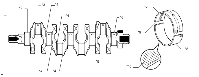
Text in Illustration *1 Crankshaft *2 No. 1 Journal *3 Oil Hole *4 Roll-finished *5 Balance Weight *6 No. 5 Journal *7 Upper Main Bearing *8 Lower Main Bearing *9 Oil Groove *10 Micro-grooved
-
-
Balance Shaft
-
For in-line 4-cylinder engines, the main cause of vibration is the imbalanced inertial force of reciprocating parts, such as the pistons and connecting rods. Engine vibration has been reduced by using 2 balance shafts to cancel the imbalanced inertial force, thereby reducing engine noise (booming noise).
-
These balance shafts are built into the cylinder block. Driven by the timing gear, the balance shafts rotate at twice the speed of the crankshaft and in the opposite direction of each other.
Text in Illustration *1 No. 1 Balance Shaft Sub-assembly *2 No. 2 Balance Shaft Sub-assembly *3 Supply Pump Drive Gear *4 Idle Gear *5 Crankshaft Timing Gear *6 Oil Pump Drive Gear
-
-
Oil Pan
-
The oil pan sub-assembly material is made of aluminum alloy.
-
The oil passage has been integrated in the oil pan to simplify the construction of the oil strainer.
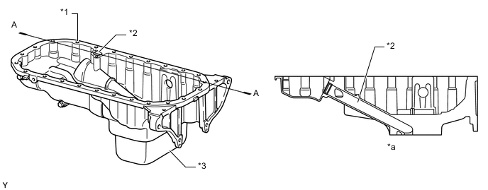
Text in Illustration *1 Oil Pan Sub-assembly *2 Oil Passage *3 No. 2 Oil Pan Sub-assembly - - *a A - A Cross Section - -
-
-
Valve Mechanism
-
Each cylinder has 2 intake valves and 2 exhaust valves. Intake and exhaust efficiency is increased by means of the larger total port areas.
-
The valves are directly opened and closed by 2 camshafts.
-
The camshaft (intake camshaft) is driven by a timing belt, while the No. 2 camshaft (exhaust camshaft) is driven by gears on the camshaft (intake camshaft).
-
Small-diameter, flat-teeth gears are used for driving the No. 2 camshaft (exhaust camshaft) in order to reduce gear noise.
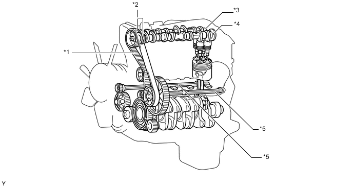
Text in Illustration *1 Timing Belt *2 Camshaft Drive Gear *3 No. 2 Camshaft (Exhaust Camshaft) *4 Camshaft (Intake Camshaft) *5 Balance Shaft - -
-
-
Camshaft
-
The cam nose has been chill-treated to increase its abrasion resistance.
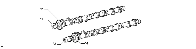
Text in Illustration *1 No. 2 Camshaft (Exhaust Camshaft) *2 Camshaft Driven Gear *3 Camshaft (Intake Camshaft) *4 Camshaft Drive Gear 
Chill-treated - -
-
-
Intake and Exhaust Valves
-
Along with the increased amount of valve lift, shim-less valve lifters that provide a large cam contact surface are used.
-
The adjustment of the valve clearance is accomplished by selecting and replacing the appropriate valve lifters.
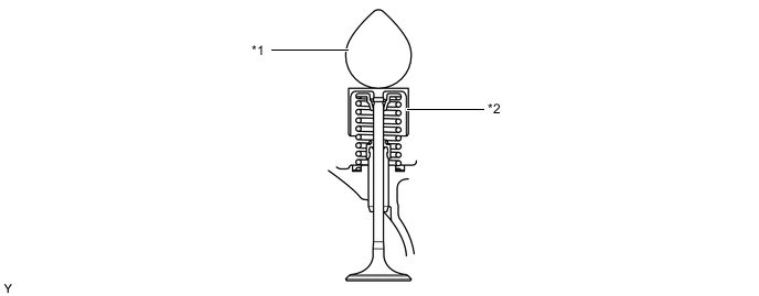
Text in Illustration *1 Camshaft *2 Valve Lifter Tech Tips
The valve lifters must be replaced when it is necessary to adjust the valve clearance. For this purpose, valve lifters with different thicknesses are available as service parts. For details, refer to the Repair Manual.
-
-
Timing Gear Train
-
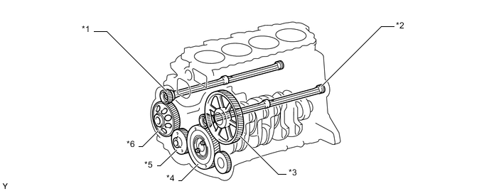
The supply pump, vacuum pump, oil pump and balance shafts are driven by the crankshaft timing gear.
-
The idle gear is constructed with a scissors gear on its front and back to reduce noise.
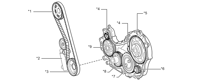
Text in Illustration *1 No. 2 Camshaft Timing Pulley *2 Automatic Tensioner *3 No. 1 Camshaft Timing Pulley *4 Balance Shaft Drive Gear *5 Supply Pump Drive Gear *6 Vacuum Pump Drive Gear *7 Idle Gear *8 Crankshaft Timing Gear *9 Oil Pump Drive Gear - -
-
-
Timing Gear Cover
-
A crank position sensor and camshaft position sensor are mounted on the timing gear cover.
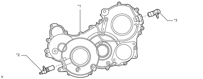
Text in Illustration *1 Timing Gear Cover *2 Crank Position Sensor *3 Camshaft Position Sensor - -
-
-
V-ribbed Belt
-
Accessory components are driven by a serpentine belt consisting of a single V-ribbed belt. This reduces the overall engine length, weight and the number of engine parts.
-
An automatic tensioner eliminates the need for tension adjustment.
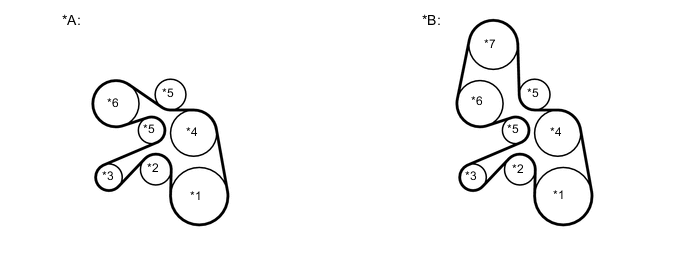
Text in Illustration *A Models without Power Heater *B Models with Power Heater *1 Crankshaft Pulley *2 Idler Pulley for Automatic Tensioner *3 Generator Pulley *4 Water Pump Pulley *5 Idler Pulley *6 Air Conditioning Compressor Pulley *7 Power Heater Pulley - -
-
-
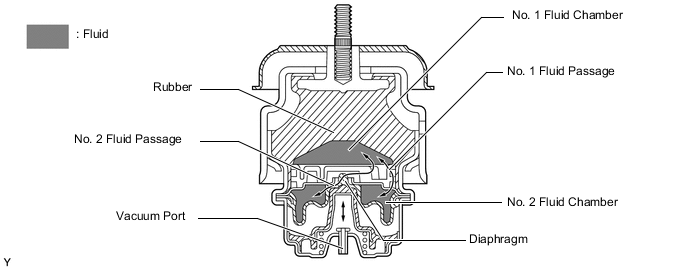
Engine Mount
-
Electrical hydraulic type engine mounts are used for the front engine mounts.
-
The front engine mount consists primarily of the rubber portion, No. 1 fluid chamber, No. 2 fluid chamber, and diaphragm. Fluid is sealed in the No. 1 and No. 2 fluid chambers.
-
This engine mount obtains a vacuum from the vacuum pump via the VSV. It utilizes the vacuum to pull the diaphragm down in order to open or close the passages that connect the No. 1 and No. 2 fluid chambers.
-
The No. 1 and No. 2 fluid chambers use two fluid passages: the No. 1 fluid passage that is always connected regardless of whether the diaphragm is open or closed; and the No. 2 fluid passage that is connected only when the diaphragm is open. The fluid flows back and forth between the No. 1 and No. 2 fluid chambers through these two passages in order to restrain the vibration.
-
-
-
OPERATION
-
Balance Shaft
-
In the in-line 4-cylinder engine, the crankshaft angle for No. 1 and No. 4 cylinders are at the exact opposite (180°) positions of No. 2 and No. 3 cylinders. Therefore, the inertial force of the pistons and the connecting rods of the former 2 cylinders and of the latter 2 cylinders almost cancel each other out. However, because the position at which the piston reaches its maximum speed is located toward the top dead center from the center of the stroke, the upward inertial force is greater than the downward inertial force. This unbalanced secondary inertial force is generated twice for each rotation of the crankshaft.
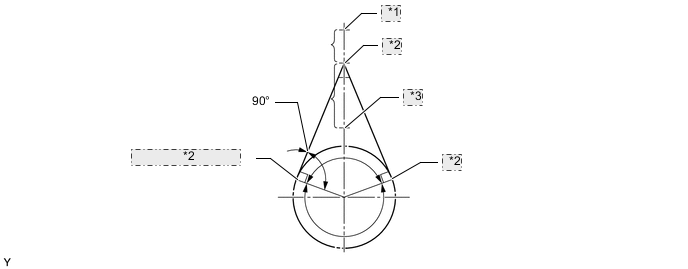
*1 Top Dead Center *2 Point of Max. Speed *3 Bottom Dead Center 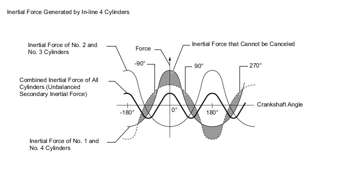
-
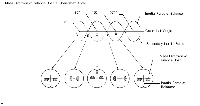
To cancel the unbalanced secondary inertial force, 2 balance shafts are rotated twice for each rotation of the crankshaft and generate inertial force in the opposite direction. Also, in order to cancel the inertial force generated by the balance shaft itself, the balance shaft actually consists of 2 shafts rotating in opposite directions.
-
-