ECD SYSTEM
-
FUNCTION OF MAIN COMPONENTS
-
The main components of the engine control system are as follows:
Component Function ECM The ECM performs overall control of the engine control system to suit the operating conditions of the engine in accordance with the signals provided by the sensors. Crank Position Sensor This sensor detects the engine speed and performs cylinder identification. Cam Position Sensor (Crank Position Sensor) This sensor performs cylinder identification. Fuel Pressure Sensor This sensor uses built-in semiconductors to detect the internal pressure of the common-rail. Intake Mass Air Flow Meter Sensor Sub-assembly This sensor uses a built-in silicon chip to directly detect the intake air mass. Inlet Air Temperature Sensor This sensor detects the intake air temperature past the intercooler. Diesel Throttle Body Assembly Throttle Position Sensor This sensor detects the diesel throttle valve opening angle. Throttle Motor Controls the throttle valve opening according to signals from the ECM. Turbo Pressure Sensor This sensor uses built-in semiconductors to detect the intake manifold pressure. Turbocharger Sub-assembly Nozzle Vane Position Sensor This sensor detects the nozzle vane position. DC Motor Controls the variable nozzle vane according to signals from the ECM. Engine Coolant Temperature Sensor This sensor detects the engine coolant temperature by means of an internal thermistor. Glow Plug Controller The glow plug controller controls the operating temperature and the operating temperature and the length of time for which the current is applied to the glow plug assemblies in accordance with the ECM signal. Injector Assembly The injector injects the fuel to the combustion chamber in accordance with the ECM signals. Pre-stroke Control Valve Assembly Regulates the pre-stroke quantity according to signals from the ECM. Pressure Discharge Valve The pressure discharge valve regulates the fuel pressure. EGR Valve Position Sensor Detects the EGR valve position and sends signals to the ECM. Exhaust Gas Temperature Sensor Detects the temperature of the exhaust gas. No. 2 Exhaust Gas Temperature Sensor No. 3 Exhaust Gas Temperature Sensor No. 4 Exhaust Gas Temperature Sensor* Air Fuel Ratio Sensor Detects the oxygen concentration in exhaust gas. NOx Sensor (Nitrogen Oxides Sensor)* Detects the concentration of NOx in the exhaust gas. Differential Pressure Sensor Detects the difference in pressure before and after the converter assembly. Exhaust Fuel Addition Injector Assembly Adds fuel inside the exhaust manifold. UREA Pump Control ECU* Controls the UREA SCR system based on various signals.
-
*: Models with UREA SCR system
-
-
-
SYSTEM CONTROL
-
The engine control system has the following features. The ECM controls these systems:
System Outline Fuel Injection Volume Control Based on the signals received from the sensors, the ECM determines the fuel injection volume in accordance with the engine condition. Fuel Injection Timing Control Based on the signals received from the sensors, the ECM determines the fuel injection timing in accordance with the engine condition. During Starting Control To facilitate startability, the ECM optimally controls the injection volume and injection timing during starting. Idle Speed Control The ECM determines the idle speed in accordance with the engine condition, and controls the fuel injection volume in order to maintain the target idle speed. Fuel Pressure Control Based on the signals received from the sensors, the ECM controls fuel pressure using the prestroke control valve in accordance with engine operating conditions. Pilot Injection Control Based on the signals received from the sensors, the ECM determines pilot injection volume/ timing and interval (between pilot injection and main injection) in accordance with the engine condition. Glow Plug Control The ECM controls the length of time for which current is applied to the glow plug assemblies, in accordance with the engine coolant temperature. Diesel Throttle Control
-
Controls the diesel throttle valve opening angle in accordance with the engine condition.
-
Fully closes the diesel throttle valve in order to reduce vibrations when the engine is stopped.
Turbocharger Control Based on the signals received from the sensors, the ECM controls the actuator in accordance with the engine condition. Swirl Control Based on the signals received from the sensors, the ECM controls the vacuum that is directed to the actuator via the VSV, in order to open and close the valve. Controls the valve opening in 2 stages: fully open and fully closed. Engine Mount Control When the engine speed is low and the vehicle is operating at a low speed, this control utilizes vacuum to soften the engine mount characteristics in order to restrain the engine vibration at idle. EGR System Based on the signals received from the sensors, the ECM determines the EGR volume via the electric EGR control valve assembly and No. 2 EGR valve assembly in accordance with the engine condition. For details, see the EMISSION CONTROL SYSTEM section. Fuel Pump Control*1 The ECM operates the fuel pump to optimally control the transfer of the fuel in the fuel tank. Oil Maintenance Management System*2 The oil maintenance information message is shown on the multi-information display according to the vehicle condition to inform the driver. For details, see the METER / GAUGE / DISPLAY section. Catalyst Support Control Based on the signals received from the sensors, the ECM controls the exhaust fuel addition injector assembly to purify the Particulate Matter (PM). For details, see the EMISSION CONTROL SYSTEM section. UREA SCR System*3 The ECM operates the urea pump according to signals from various sensors to control the urea addition amount. Also, the ECM determines how much urea solution is remaining and whether urea solution needs to be refilled or not according to signals from the urea level sensor, and sends display signals to the combination meter assembly depending on the situation. For details, see the EMISSION CONTROL SYSTEM section. Air Conditioning Cut-off Control By controlling the air conditioning compressor on or off in accordance with the engine condition, driveability is maintained. Immobiliser System Prohibits fuel injection if an attempt is made to start the engine with an invalid ignition key. Drive Start Control If an abnormal shift (R to D, D to R, N to R, P to D, P to R) is detected while accelerating, a warning is displayed in the combination meter assembly and engine output is reduced to limit the acceleration, helping to avoid a collision. Brake Override System The driving torque is restricted when both the accelerator and brake pedals are depressed. (For the Activation Conditions and Inspection Method, refer to the repair manual.) Diagnosis When the ECM detects a malfunction, it diagnoses and memorizes the failed section. Fail-safe When the ECM detects a malfunction, it stops or controls the engine in accordance with the data already stored in the memory.
-
*1: Models with dual fuel tank
-
*2: Models for Europe
-
*3: Models compliant with EURO 6 emission regulation
-
-
-
FUNCTION
-
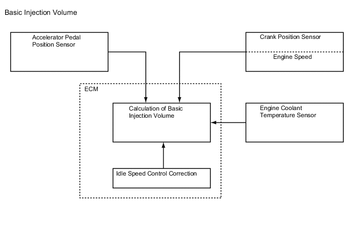
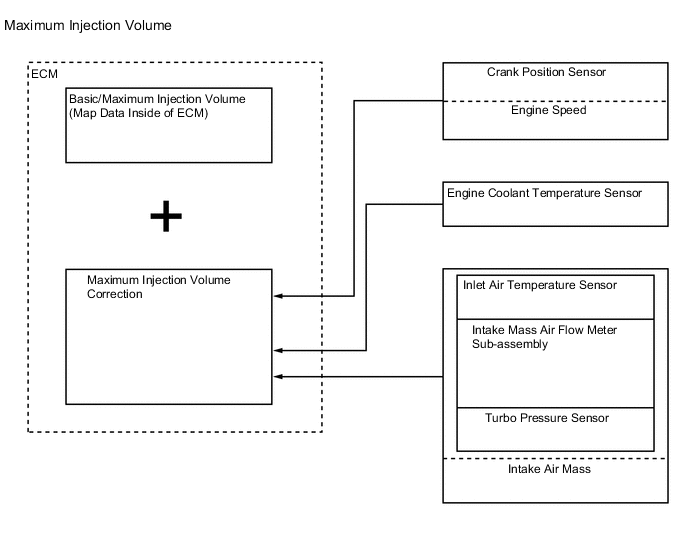
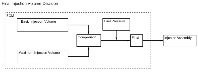
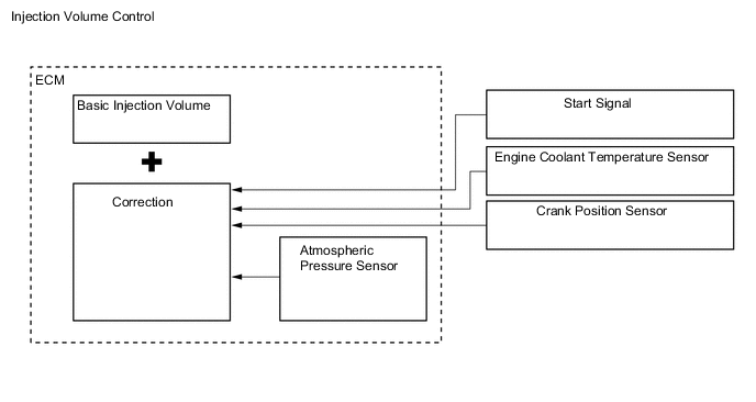
Fuel Injection Volume Control
-
The ECM calculates 2 types of values: the basic injection volume and the maximum injection volume. Then, the ECM compares the basic and maximum injection volumes, and determines the smaller calculated value to be the final injection volume.
-
-
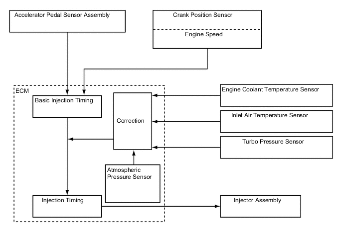
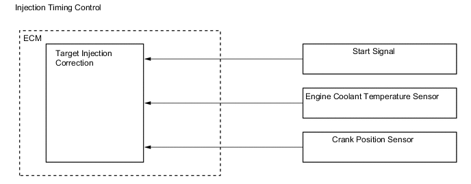
Fuel Injection Timing Control
-
Fuel injection timing is controlled as shown below:
-
-
During Starting Control
-
The starting injection volume is determined by adjusting the basic injection volume in accordance with the starter on signals (on time), engine coolant temperature sensor signals and engine speed signals. When the engine is cold, the engine coolant temperature will be lower and the injection volume will be greater.
-
To determine the starting injection timing, the target injection timing is corrected in accordance with the starter signals, engine coolant temperature and engine speed. When the engine coolant temperature is low, if the engine speed is high, the injection timing is advanced.
-
-
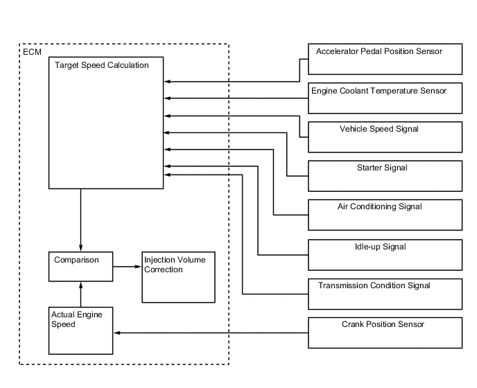
Idle Speed Control
-
Idle speed control correction is controlled as shown below:
-
-
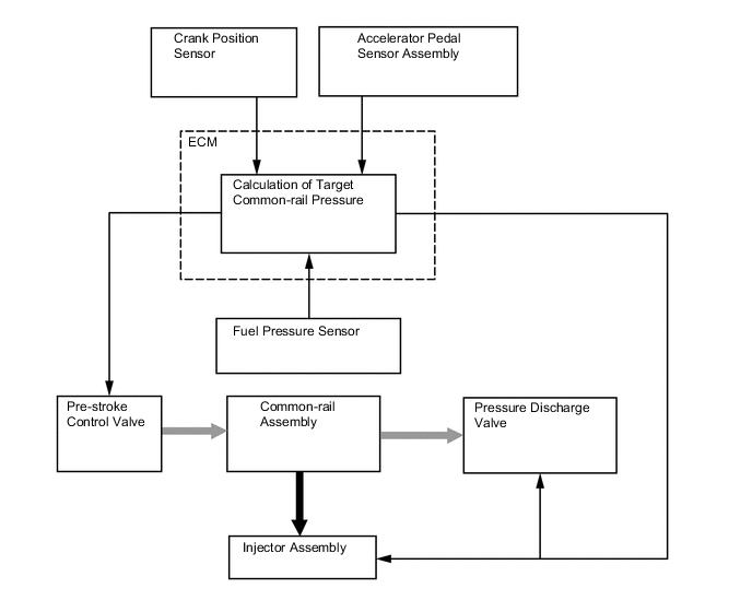
Fuel Pressure Control
-
The ECM calculates the target injection pressure (35 MPa to 220 MPa) based on the signals from the accelerator pedal sensor assembly and the crank position sensor. To control fuel pressure, signals sent to the prestroke control valve of the supply pump assembly regulate the delivery volume, and signals sent to the pressure discharge valve of the common-rail regulate the relief volume, so that the pressure detected by the fuel pressure sensor matches the target injection pressure.
-
-
Pilot Injection Control
-
Pilot injection is a method that provides auxiliary fuel injection before main fuel injection takes place. The purpose of pilot injection is to gently start the combustion of the fuel of the main injection in order to reduce combustion noise.
State Pilot Injection Ordinary Injection Fuel Injection 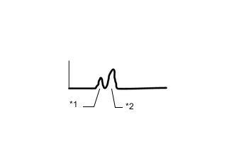
*1 Pilot Injection *2 Main Injection 
Combustion Pressure 
-
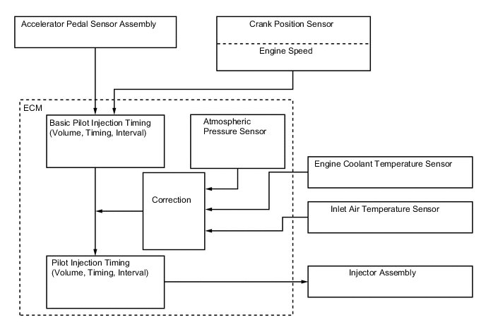
During pilot injection, the pilot injection volume, timing and interval (between pilot injection and main injection) are controlled as shown below:
-
-
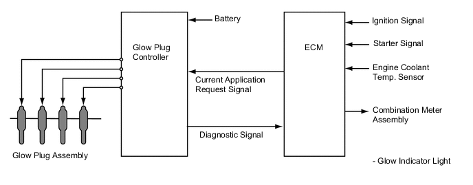
Glow Plug Control
-
The ECM sends signals to the glow plug controller, and the glow plug controller controls the operating temperature and the length of time for which current is applied to the glow plug assemblies in accordance with the engine conditions. By precisely controlling the temperature inside cylinder, low emissions are achieved.
-
The glow plug control carries out the following controls:
-
When the ignition switch is turned from off to on, the ECM sends a signal to the glow plug controller. Based on this signal, the glow plug controller heats the glow plug assemblies rapidly. At this moment, the glow indicator light in the combination meter is illuminated to inform the driver that the glow plug assemblies are being heated.
-
When the engine starts and the starter signal is off, after-glow control is conducted.
-
In accordance with signals from the ECM, the glow plug controller applies current via the glow plug assembly to control the temperature of cylinder.
-
When the glow plug controller detects a malfunction in the glow circuit, it sends a diagnostic signal to the ECM.
-
-
-
Diesel Throttle Control
-
The ECM controls the opening of the diesel throttle valve to reduce the noise caused when idling and decelerating, and the noise and vibrations caused when stopping the engine.
-
The opening of the diesel throttle valve is controlled by the ECM in accordance with the engine conditions. As a result, the noise that is generated during idling and deceleration, as well as the noise and vibrations that are generated when the engine is stopped, have been reduced and this control makes it possible to recirculate exhaust gas in accordance with the driving conditions.
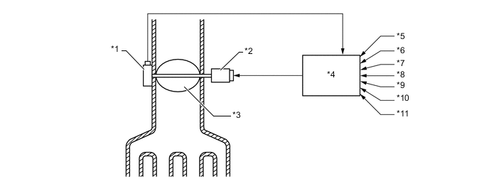
Text in Illustration *1 Throttle Position Sensor *2 Throttle Control Motor *3 Diesel Throttle Valve *4 ECM *5 Engine Speed Signal *6 Vehicle Speed Signal *7 Engine Coolant Temperature Signal *8 Intake Air Temperature Signal *9 Accelerator Pedal Position Signal *10 Intake Air Pressure Signal *11 Ignition Signal - -
-
-
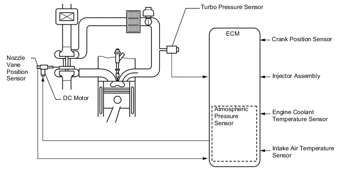
Turbocharger Control
-
The ECM controls the nozzle vane position in order to obtain the calculated target turbo pressure appropriate for the engine operating conditions.
-
The turbocharger control carries out the following controls:
-
The ECM calculates the optimal nozzle vane position in accordance with the driving conditions (engine speed, injection volume, atmospheric pressure, engine coolant temperature, etc.), and controls the nozzle vane position in accordance with the optimal nozzle vane position and the actual nozzle vane position signal provided by the nozzle vane position sensor.
-
-
-
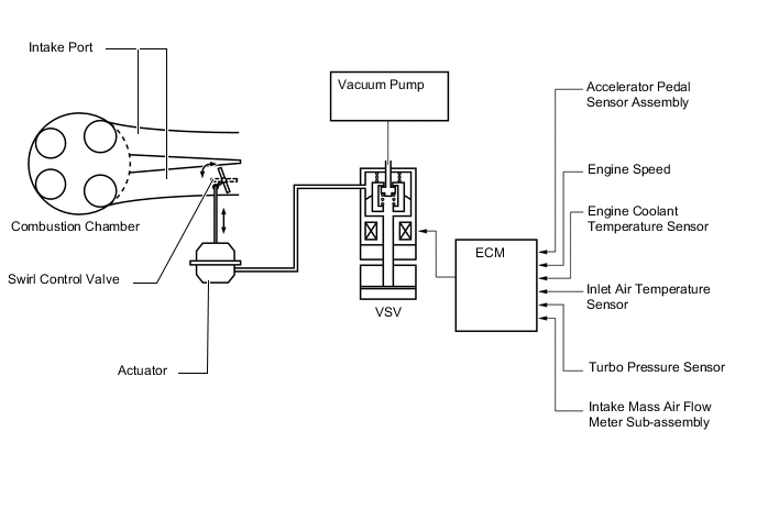
Swirl Control
-
The ECM controls the swirl control valve position to optimize exhaust emissions.
-
-
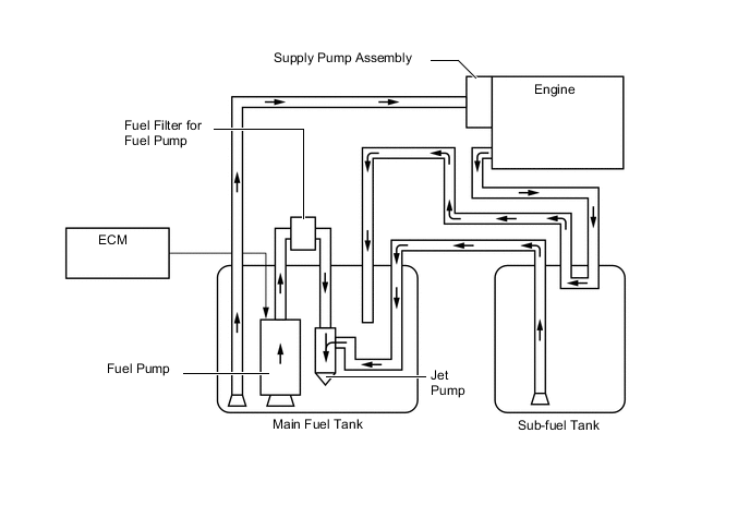
Fuel Pump Control (Models with Dual Fuel Tank)
-
The fuel pump control system transfers fuel from the sub fuel tank to the main fuel tank.
-
The supply pump assembly delivers fuel from the main fuel tank to the engine. Therefore, fuel in sub fuel tank needs to be transferred to the main fuel tank. In this system, the ECM operates the fuel pump to transfer the fuel from the sub fuel tank to the main fuel tank using the jet pump built into the fuel pump.
-
-
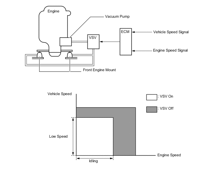
Engine Mount Control
-
When the engine is idling and the vehicle is operating at a low speed, this engine mount utilizes the vacuum from the vacuum pump (for the engine) to move the diaphragm in the mount, which switches the passages for the fluid (water) that is sealed in. By softening the dampening characteristics of the mount in this manner, this mount restrains engine vibration.
-
The ECM determines the idling state of the engine and the low speed state of the vehicle in accordance with the engine speed and the vehicle speed. Thus, the ECM controls the introduction of vacuum from the vacuum pump (for the engine) to the engine mount by turning the VSV on or off.
-
A hysteresis is provided for both the engine speed and the vehicle speed at the point in which the VSV switches from on to off.
-
While the engine is cranking, the VSV is off.
-
When the ECM determines that the engine speed is anything other than idle in accordance with the engine speed and the vehicle speed, it stops the introduction of vacuum into the engine mount by turning the VSV off.
-
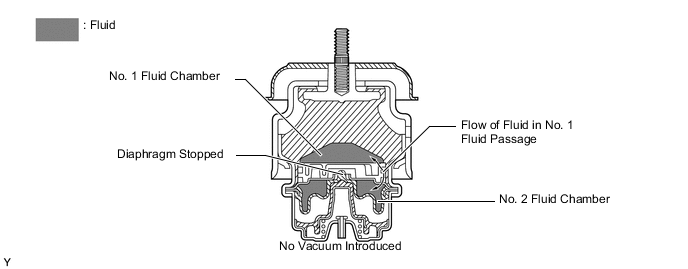
When no vacuum is introduced into the engine mount, the diaphragm does not move, so the No. 1 fluid passage remains closed. In this state, the fluid passes only through the No. 1 fluid passage in order to flow back and forth between the No. 1 and No. 2 fluid chambers.
-
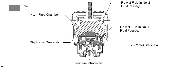
When the ECM determines via the engine speed and the vehicle speed that the engine is idling, it turns the VSV on to introduce vacuum into the engine mount.
-
When a vacuum is introduced into the engine mount, it pulls the diaphragm down, causing the No. 2 fluid passage to open. As a result, a large volume of fluid flows back and forth between the No. 1 and No. 2 fluid chambers, thus minimizing the fluid resistance and softening the engine mount characteristics.
-
-
Drive Start Control
-
When abnormal driver accelerator pedal and shift operations are detected, the system limits the engine output and informs the driver.
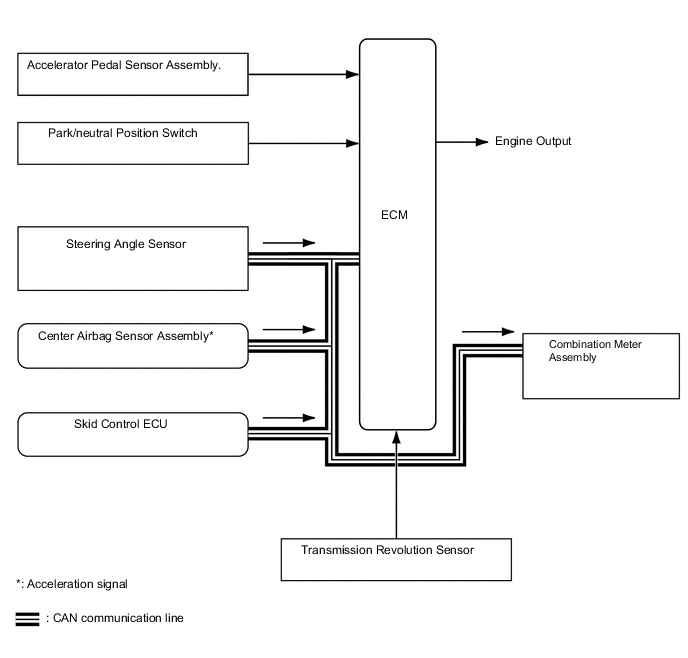
Tech Tips
-
When the VSC OFF switch is operated to turn the VSC off, the drive start control system does not operate.
-
When 4WD is L4 position by 4WD switch, the drive start control system does not operate.
-
When Center Differential Lock Mechanism is locked by Center Differential Lock switch, the drive start control system does not operate.
-
When the system is operating, even if the driver depresses and holds the accelerator pedal, engine output may increase on an uphill slope and decrease on a downhill slope. This behavior allows the system to restrict the vehicle speed and acceleration below the predetermined limit on slopes and is not a malfunction.
-
-
Control during Shift Operation
-
Responds to shift operations with the accelerator pedal depressed.
-
Changes the limit amount according to the manual shift operation pattern.
-
Corrects engine output according to the road grade and steering angle.
-
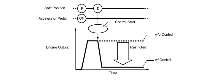
Control when Starting Off from a Parked Position
Control Start Conditions (When all of the following conditions are met, control starts.)
-
Shift position is changed from P to D, or P to R.
-
Accelerator pedal is depressed.
Control Operation Restricts the engine output so the vehicle speed and acceleration are at or below a certain level. Control Stop Conditions (Control stops when any of the conditions are met.)
-
Accelerator pedal is fully released.
-
Shift position is P or N.
-
-
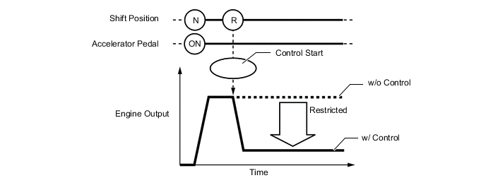
Control during Other Situations
Control Start Conditions (When all of the following conditions are met, control starts.)
-
Shift position is changed from R to D, D to R, or N to R.
-
Accelerator pedal is depressed.
Control Operation Restricts the engine output so the vehicle speed and acceleration are at or below a certain level. Control Stop Conditions (Control stops when any of the conditions are met.)
-
Accelerator pedal is fully released.
-
Shift position is P or N.
Tech Tips
-
The engine output restraint level differs in the above 2 situations.
-
During control while a manual shift operation is performed (from control start until the accelerator pedal is released), the system informs the driver of the control via the multi-information display. For details, see COMBINATION METER in the METER / GAUGE / DISPLAY section.
-
-
-
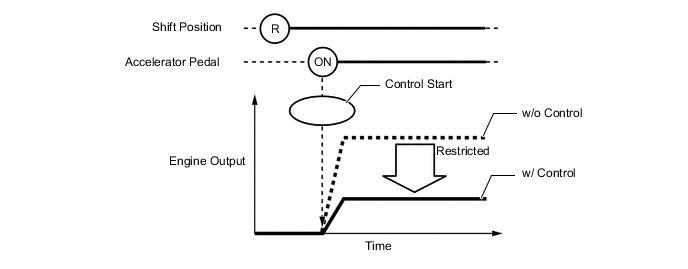
Control during Reverse Operation
-
Responds to excessive depression of the accelerator pedal while operating in reverse.
-
Corrects engine output according to the road grade and steering angle.
Control Start Conditions (When all of the following conditions are met, control starts.)
-
Shift position is R.
-
Accelerator pedal is depressed.
Control Operation Restricts the engine output so the vehicle speed and acceleration are at or below a certain level. Control Stop Conditions (Control stops when any of the conditions are met.)
-
Accelerator pedal is fully released.
-
Shift position is not R.
-
-
-
-
-
CONSTRUCTION
-
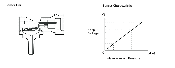
Turbo Pressure Sensor
-
The turbo pressure sensor consists of a semiconductor which utilizes the characteristics of a silicon chip that changes its electrical resistance when pressure is applied to it. The sensor converts the intake air pressure into an electrical signal, and sends it to the ECM in an amplified form.
-
-
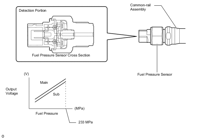
Fuel Pressure Sensor
-
The fuel pressure sensor, which is mounted on the common-rail, outputs a signal that represents the fuel pressure in the common-rail to the ECM in order to constantly regulate the fuel at an optimal pressure.
-
The fuel pressure sensor consists of a semiconductor which utilizes the characteristics of a silicon chip that changes its electrical resistance when pressure is applied to it.
-
The fuel pressure sensor has 2 circuits (main and sub), which enable the ECM to constantly compare the values detected by the 2 circuits. As a result, highly precise values can be detected, which also enables a higher level of fail-safe control.
-
-
Pressure Discharge Valve
-
The pressure discharge valve regulates the fuel pressure. In the pressure discharge valve, the plunger opens and closes in accordance with the actuation signals from the ECM. Thus, it regulates pressure by releasing excess pressure from the common-rail. In addition, it has a pressure reduction function in case of emergency.
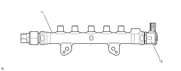
Text in Illustration *1 Common-rail Assembly *2 Pressure Discharge Valve
-
-
Crankshaft Position Sensor
-
A Magnetic Resistance Element (MRE) type crank position sensor is used. The timing rotor of the crankshaft consists of 34 teeth with 2 teeth missing. The crank position sensor outputs the crankshaft rotation signals every 10°, and the missing teeth are used to determine the top dead center.

Text in Illustration *1 Crank Position Sensor *2 Timing Rotor
-
-
Camshaft Position Sensor
-
A Magnetic Resistance Element (MRE) type cam position sensor is used. To detect the camshaft position, a timing rotor on the exhaust camshaft is used to generate 3 (3 high output, 3 low output) pulses for every 2 revolutions of the crankshaft.
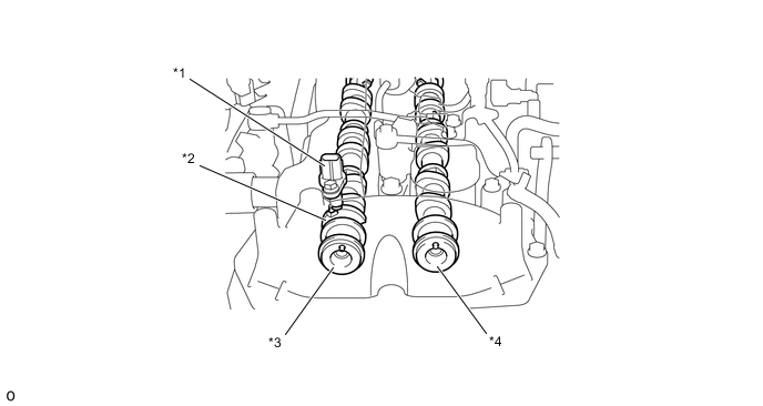
Text in Illustration *1 Cam Position Sensor (Crank Position Sensor) *2 Timing Rotor *3 Exhaust Camshaft *4 Intake Camshaft
-
-
Mass Air Flow Meter
-
This mass air flow meter, which is a slot-in type, allows a portion of the intake air to flow through the detection area. By directly measuring the mass flow rate of the intake air, the detection precision is improved and the intake air resistance is reduced.
-
This intake mass air flow meter sub-assembly has a built-in intake air temperature sensor.
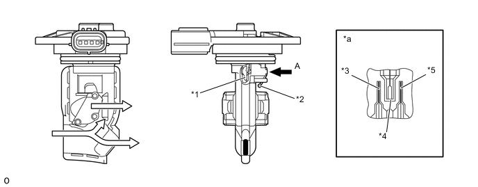
Text in Illustration *1 Silicon Chip *2 Intake Air Temperature Sensor *3 Upper Stream Temperature Sensing Element *4 Heater *5 Down Stream Temperature Sensing Element - - *a View from A - -
-
-
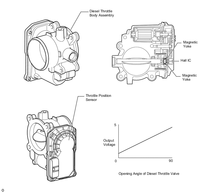
Throttle Position Sensor
-
The throttle position sensor is mounted on the diesel throttle body assembly. To detect the opening angle of the diesel throttle valve, the throttle position sensor converts the magnetic flux density, which changes when the magnetic yoke (located on the same axis as the diesel throttle valve shaft) rotates around the Hall IC, into electric signals to operate the throttle control motor.
-
-
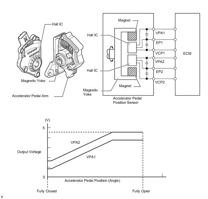
Accelerator Pedal Position Sensor
-
The magnetic yoke that is mounted at the base of the accelerator pedal arm moves around the Hall IC in accordance with the amount of effort that is applied to the accelerator pedal. The Hall IC converts the changes in the magnetic flux that occur at that time into electrical signals, and outputs them in the form of accelerator pedal effort to the ECM
-
-
Glow Plug Controller
-
The glow plug controller controls the operating temperature and the length of time for which current is applied to the glow plug assemblies in accordance with signals from the ECM.
-
The glow plug controller has a function to detect open circuits in the glow plug assemblies. When the glow plug controller detects an open circuit in a glow plug assembly, it sends a signal to the ECM.
-
-