SFI SYSTEM
-
FUNCTION OF MAIN COMPONENTS
-
The main components of the engine control system are as follows:
Component Outline Quantity Function ECM 32-bit CPU 1 The ECM optimally controls the SFI, ESA and ISC to suit the operating conditions of the engine in accordance with the signals provided by the sensors. Intake Air Flow Meter Sub-assembly Hot-wire Type 1 This sensor has a built-in hot-wire to directly detect the intake air mass. Intake Air Temperature Sensor Thermistor Type 1 This sensor detects the intake air temperature by means of an internal thermistor. Engine Coolant Temperature Sensor Thermistor Type 1 This sensor detects the engine coolant temperature by means of an internal thermistor. Crankshaft Position Sensor [Rotor Teeth] Pick-up Coil Type [36 - 2] 1 This sensor detects the engine speed and performs cylinder identification. Camshaft Position Sensor for Intake [Rotor Teeth] Magnetic Resistance Element (MRE) Type [3] 2 (1 each bank) This sensor performs cylinder identification. Camshaft Position Sensor for Exhaust [Rotor Teeth] Magnetic Resistance Element (MRE) Type [3] 2 (1 each bank) This sensor performs cylinder identification. Accelerator Pedal Position Sensor Linear (Non-contact) Type 1 This sensor detects the amount of pedal effort applied to the accelerator pedal. Throttle Position Sensor Linear (Non-contact) Type 1 This sensor detects the throttle valve opening angle. Knock Control Sensor (Bank 1 and Bank 2) Built-in Piezoelectric Type (Non-resonant Type/ Flat Type) 2 (1 each bank) This sensor detects an occurrence of engine knocking indirectly from the vibration of the cylinder block caused by the occurrence of engine knocking. Air Fuel Ratio Sensor (Bank 1, Sensor 1) (Bank 2, Sensor 1) Heated Type (Planar Type) 2 (1 each bank) As with the oxygen sensor, this sensor detects the oxygen concentration in the exhaust emission. However, it detects the oxygen concentration in the exhaust emission linearly. Oxygen Sensor (Bank 1, Sensor 2) (Bank 2, Sensor 2) Heated Type (Cup Type) 2 (1 each bank) This sensor detects the oxygen concentration in the exhaust emission by measuring the electromotive force which is generated in the sensor itself. Fuel Injector Assembly 12-hole Type 6 The fuel injector assembly is an electromagnetically-operated nozzle which injects fuel in accordance with signals from the ECM.
-
-
SYSTEM CONTROL
-
The engine control system has the following features. The ECM controls these systems:
System Outline Sequential Multiport Fuel Injection (SFI)
-
An L-type SFI system directly detects the intake air mass with a hot-wire type mass air flow meter.
-
The fuel injection system is a sequential multiport fuel injection system.
Electronic Spark Advance (ESA)
-
Ignition timing is determined by the ECM based on signals from various sensors. The ECM corrects ignition timing in response to engine knocking.
-
This system selects the optimal ignition timing in accordance with the signals received from the sensors and sends (IGT) ignition signals to the igniters.
Electronic Throttle Control System-intelligent (ETCS-i) Optimally controls the throttle valve opening in accordance with the amount of accelerator pedal effort, the throttle valve opening control request from the ECM, and the condition of the engine and the vehicle. Dual Variable Valve Timing-intelligent (Dual VVT-i) Regulates operation of the intake and exhaust camshafts to ensure an optimal valve timing in accordance with the engine condition. Fuel Pump Control
-
Based on signals from the ECM, the fuel pump control ECU controls the fuel pump in 3 stages.
-
The fuel pump is stopped when the SRS airbag is deployed in a frontal, side, or side rear collision.
Air Conditioning Cut-off Control By turning the air conditioning compressor assembly on or off in accordance with the engine condition, driveability is maintained. Starter Control Once the engine switch is pushed, this control continues to operate the starter until the engine has started. Air Fuel Ratio Sensor and Oxygen Sensor Heater Control Maintains the temperature of the air fuel ratio sensors or oxygen sensors at an appropriate level to increase the detection accuracy of the exhaust gas oxygen concentration. Engine Immobiliser Prohibits fuel delivery and ignition if an attempt is made to start the engine with an invalid key. Diagnosis When the ECM detects a malfunction, the ECM diagnoses and memorizes the failed section. Fail-safe When the ECM detects a malfunction, the ECM stops or controls the engine in accordance with the data already stored in memory. Drive Start Control If an abnormal shift (R to D/S, D/S to R, N to R, P to D/S, P to R) is detected while accelerating, a warning is displayed in the combination meter assembly and driving force is reduced to limit the acceleration, helping to avoid a collision. Brake Override System The driving torque is restricted when both the accelerator and brake pedals are depressed. (For the activation conditions and inspection method, refer to the Repair Manual.) -
-
-
FUNCTION
-
Dual VVT-i System
-
The Dual VVT-i system is designed to control the intake and exhaust camshaft within a range of 40° and 35° respectively (of crankshaft angle) to provide valve timing that is optimally suited to the engine operating conditions. This improves torque in all the speed ranges as well as increasing fuel economy, and reducing exhaust emissions.
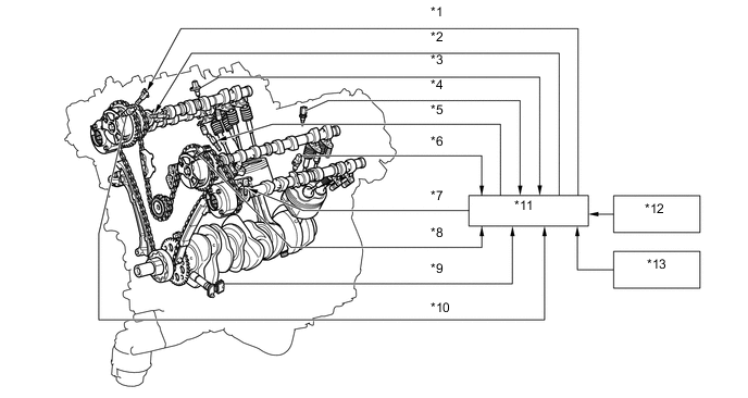
Text in Illustration *1 Camshaft Timing Oil Control Valve Assembly (Exhaust RH) *2 Camshaft Timing Oil Control Valve Assembly (Intake RH) *3 Camshaft Position Sensor (Exhaust RH) *4 Engine Coolant Temperature Sensor *5 Camshaft Timing Oil Control Valve Assembly (Intake LH) *6 Camshaft Position Sensor (Exhaust LH) *7 Camshaft Timing Oil Control Valve Assembly (Exhaust LH) *8 Camshaft Position Sensor (Intake LH) *9 Crankshaft Position Sensor *10 Camshaft Position Sensor (Intake RH) *11 ECM *12 Intake Air Flow Meter Sub-assembly *13 Throttle Position Sensor - - 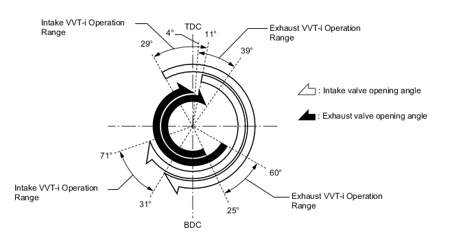
-
The VVT-i system delivers excellent benefits in the different operating conditions as shown in the table below.
Operation State Objective Effect During Idling 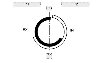
*1 Earliest Timing (EX) *2 Latest Timing (IN) *3 TDC *4 BDC Eliminating overlap reduces blow back to the intake side.
-
Stabilized idling speed
-
Better fuel economy
At Light Load 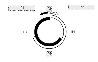
*1 Earliest Timing (EX) *2 TDC *3 Latest Timing (IN) *4 BDC Eliminating overlap reduces blow back to the intake side. Engine stability is ensured At Medium Load 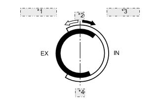
*1 To Advance Side (IN) *2 TDC *3 To Retard Side (EX) *4 BDC Increasing overlap increases internal EGR, reducing pumping losses.
-
Better fuel economy
-
Improved emission control
In Low to Medium Speed Range with Heavy Load 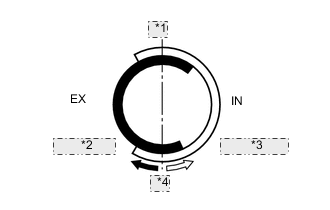
*1 TDC *2 To Retard Side (EX) *3 To Advance Side (IN) *4 BDC Advancing the intake valve closing timing improves volumetric efficiency. Improved torque in low to medium speed range In High Speed Range with Heavy Load 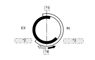
*1 TDC *2 To Retard Side (IN) *3 To Advance Side (EX) *4 BDC Retarding the intake valve closing timing improves volumetric efficiency. Improved output At Low Temperatures
*1 Earliest Timing (EX) *2 Latest Timing (IN) *3 TDC *4 BDC Eliminating overlap to reduce blow back to the intake side stabilizes the idling speed at fast idle.
-
Stabilized fast idle speed
-
Better fuel economy
-
Starting Engine
-
Stopping Engine
*1 Earliest Timing (EX) *2 Latest Timing (IN) *3 TDC *4 BDC Eliminating overlap minimize blow back to the intake side. Improved startability -
-
-
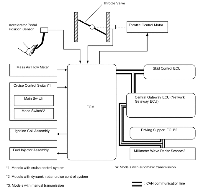
Electronic Throttle Control System-intelligent (ETCS-i)
-
The ETCS-i is used, providing excellent throttle control in all the operating ranges. The accelerator cable has been discontinued, and an accelerator pedal position sensor has been provided on the accelerator pedal.
-
In the conventional throttle body, the throttle valve opening is determined by the amount of the accelerator pedal effort. In contrast, the ETCS-i uses the ECM to calculate the optimal throttle valve opening that is appropriate for the respective driving condition and uses a throttle control motor to control the opening.
-
The ETCS-i controls the idle speed, Brake Control system, cruise control system*1 and dynamic radar cruise control system*2.
-
*1: Models with cruise control system
-
*2: Models with dynamic radar cruise control system
-
-
In case of an abnormal condition, this system switches to the limp mode.
-
-
Fuel Pump Control
-
The fuel pump is controlled by the fuel pump control ECU based on signals from the ECM. The fuel pump control has a fuel cut control. The fuel cut control stops the fuel pump when any of the Supplemental Restraint System (SRS) airbags have deployed.
-
-
Starter Control
-
Once the engine switch is pressed, this function operates the starter until the engine starts, provided that the clutch pedal is depressed.
-
This prevents application of the starter for an inadequate length of time and also prevents the engine from being cranked after it has started.
-
-
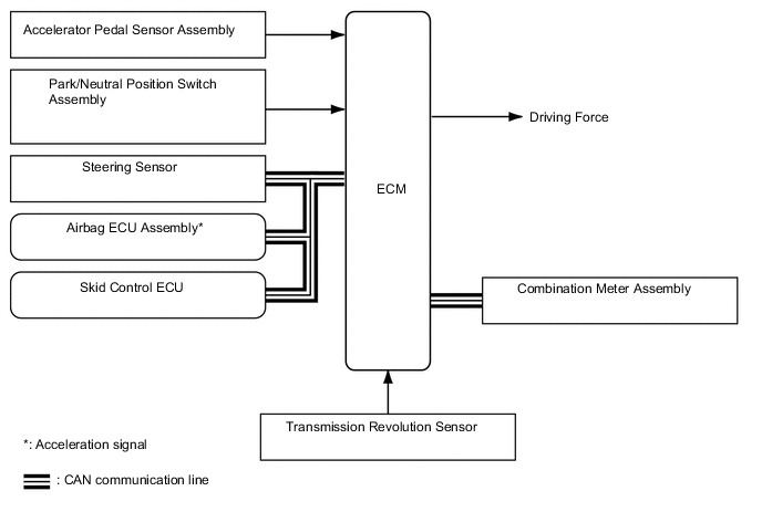
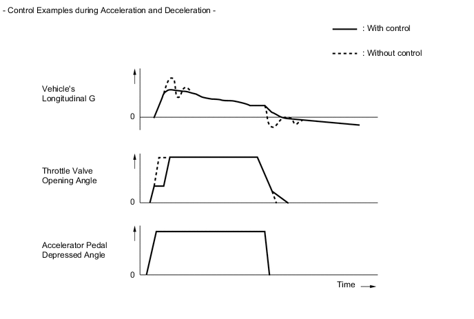
Drive Start Control
-
When abnormal driver accelerator pedal and shift operations are detected, the system limits the driving force and informs the driver.
Tech Tips
-
The drive start control does not operate, when the TRC is canceled by VSC OFF switch.
-
The drive start control does not operate, when the L4 position is selected by 4WD switch.
-
The drive start control does not operate, when the center differential lock is locked by transfer position switch.
-
When the system is operating, even if the driver depresses and holds the accelerator pedal, driving force may increase on an uphill slope and decrease on a downhill slope. This behavior allows the system to restrict the vehicle speed and acceleration below the predetermined limit on slopes and is not a malfunction.
-
-
Control during Shift Operation
-
Responds to shift operations with the accelerator pedal depressed.
-
Changes the limit amount according to the shift operation pattern.
-
Corrects driving force according to the road grade and steering angle.
-
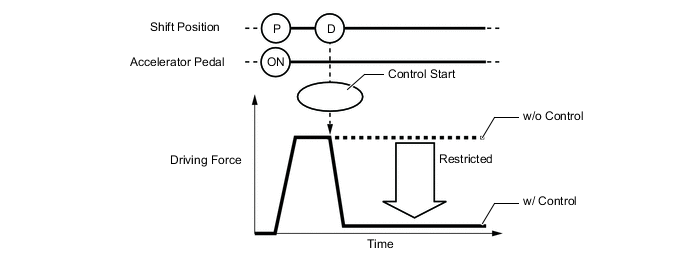
Control when Starting Off from a Parked Position
Control Start Conditions (When all of the following conditions are met, control starts.)
-
Shift position is changed from P to D/S, or P to R.
-
Accelerator opening angle is approximately 1/5 or higher.
Control Operation Restricts the driving force so the vehicle speed and acceleration are at or below a certain level. Control Stop Conditions (Control stops when any of the conditions are met.)
-
Accelerator pedal is fully released.
-
Shift position is P or N.
-
-
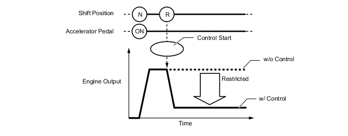
Control during Other Situations
Control Start Conditions (When all of the following conditions are met, control starts.)
-
Shift position is changed from R to D/S, D/S to R, or N to R.
-
Accelerator opening angle is approximately 1/5 or higher.
Control Operation Restricts the driving force so the vehicle speed and acceleration are at or below a certain level. Control Stop Conditions (Control stops when any of the conditions are met.)
-
Accelerator pedal is fully released.
-
Shift position is P or N.
Tech Tips
-
The driving force restraint level differs in the above 2 situations.
-
During control while a shift operation is performed (from control start until the accelerator pedal is released), the system informs the driver of the control via the multi-information display. For details, see COMBINATION METER in the METER / GAUGE / DISPLAY section.
-
-
-
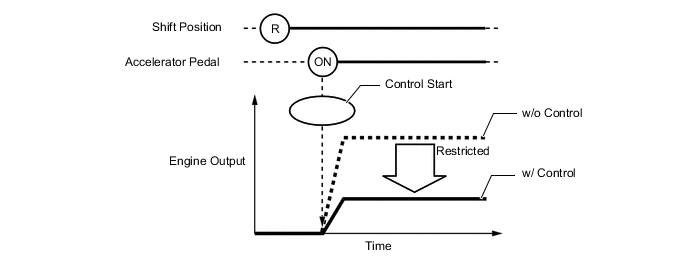
Control during Reverse Operation
-
Responds to excessive depression of the accelerator pedal while operating in reverse.
-
Corrects driving force according to the road grade and steering angle.
Control Start Conditions (When all of the following conditions are met, control starts.)
-
Shift position is R.
-
Accelerator pedal is depressed excessively.
Control Operation Restricts the driving force so the vehicle speed and acceleration are at or below a certain level. Control Stop Conditions (Control stops when any of the conditions are met.)
-
Accelerator pedal is fully released.
-
Shift position is not R.
-
-
-
-
-
CONSTRUCTION
-
Air Fuel Ratio Sensor and Oxygen Sensor
-
A planar type air fuel ratio sensor and a cup type oxygen sensor are used. The basic construction of the oxygen sensor and the air fuel ratio sensor is the same. However, they are divided into the cup type and the planar type, in accordance with the different types of heater construction used.
-
The planar type air fuel ratio sensor uses alumina, which excels in heat conductivity and electrical insulation, to integrate the sensor element with a heater, thus improving the warmup performance of the sensor.
-
The cup type oxygen sensor contains a sensor element that surrounds the heater.
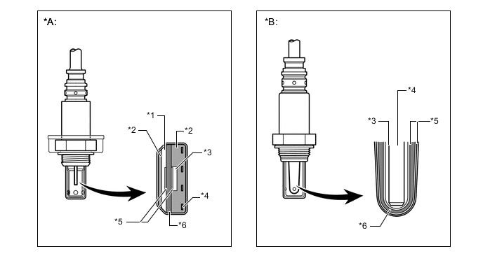
Text in Illustration *A Planar Type Air Fuel Ratio Sensor *B Cup Type Oxygen Sensor *1 Diffusion Resistance Layer *2 Alumina *3 Atmosphere *4 Heater *5 Platinum Electrode *6 Sensor Element (Zirconia) -
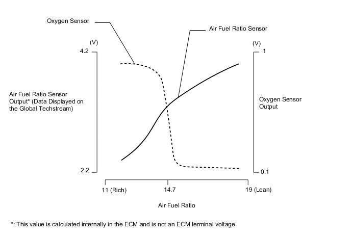
As illustrated below, the conventional oxygen sensor is characterized by a sudden change in its output voltage at the threshold of the stoichiometric air fuel ratio (14.7:1). In contrast, the air fuel ratio sensor data is approximately proportionate to the existing air fuel ratio. The air fuel ratio sensor converts the oxygen density to current and sends it to the ECM. As a result, the detection precision of the air fuel ratio has been improved. The air fuel ratio sensor data can be viewed using an the Global Techstream.
-
-
Intake Air Flow Meter Sub-assembly
-
This Intake Air Flow Meter Sub-assembly, which is a slot-in type, allows a portion of the intake air to flow through the detection area. By directly measuring the mass and the flow rate of the intake air, the detection precision is improved and the intake air resistance is reduced.
-
This Intake Air Flow Meter Sub-assembly has a built-in intake air temperature sensor.
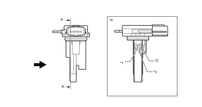
Text in Illustration *1 Platinum Hot-wire Element *2 Intake Air Temperature Sensor *3 Temperature Sensing Element - - *a A - A Cross Section - - 
Air Flow - -
-
-
Crankshaft Position Sensor
-
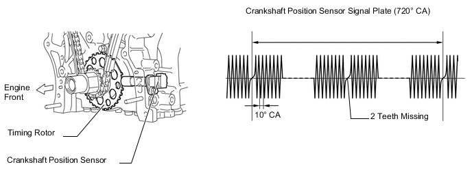
A pick-up coil type crankshaft position sensor is used. The timing rotor of the crankshaft consists of 34 teeth, with 2 teeth missing. The crankshaft position sensor outputs the crankshaft rotation signals every 10°, and the missing teeth are used to determine the top-dead-center.
-
-
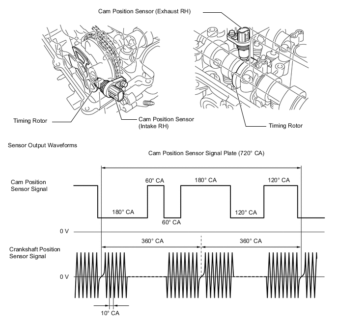
Cam Position Sensor
-
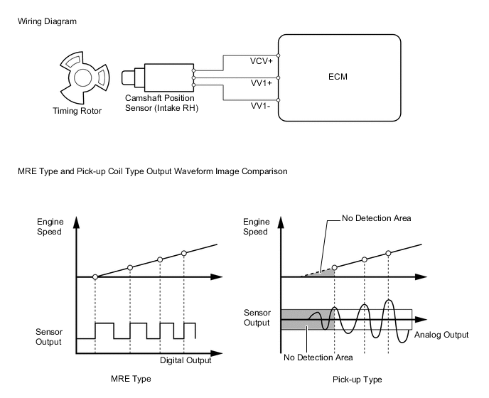
Magnetic Resistance Element (MRE) type cam position sensors (intake and exhaust) are used. To detect each cam (intake) position, a timing rotor that is secured to the camshaft (intake) in front of the camshaft timing gear assembly is used to generate 6 (3 Hi Output, 3 Lo Output) pulses for every 2 revolutions of the crankshaft. The timing rotor for each camshaft (exhaust) is part of the respective camshaft.
-
The MRE type cam position sensor consists of an MRE, a magnet and a sensor. The direction of the magnetic field changes due to the different shapes (protruded and non-protruded portions) of the timing rotor, which passes by the sensor. As a result, the resistance of the MRE changes, and the output voltage to the ECM changes to high or low. The ECM detects the cam position based on this output voltage.
-
-
Knock Control Sensor (Flat Type)
-
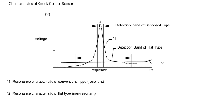
In a conventional knock control sensor (resonant type), a vibration plate is built into the sensor. This plate has the same resonance point as the knocking* frequency of the engine block. This sensor can only detect vibration in this frequency band.
-
*: The term "Knock" or "Knocking" is used in this case to describe either preignition or detonation of the air fuel mixture in the combustion chamber. This preignition or detonation refers to the air fuel mixture being ignited earlier than is advantageous. This use of "Knock" or "Knocking" is not primarily used to refer to a loud mechanical noise that may be produced by an engine.
-
-
A flat type knock control sensor (non-resonant type) has the ability to detect vibration in a wider frequency band (from approximately 6 kHz to 15 kHz). It has the following features:
-
The engine knocking frequency will vary slightly depending on the engine speed. The flat type knock control sensor can detect vibration even when the engine knocking frequency changes. Due to the use of the flat type knock control sensor, the vibration detection ability has been increased compared to a conventional type knock control sensor, and more precise ignition timing control is possible.
-
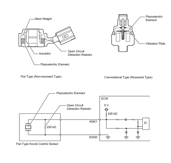
A flat type knock control sensor is installed to an engine by placing it over the stud bolt installed on the cylinder block. For this reason, a hole for the stud bolt exists in the center of the sensor.
-
In the sensor, a steel weight is located in the upper portion. An insulator is located between the weight and the piezoelectric element.
-
An open/short circuit detection resistor is integrated in the sensor. When the ignition switch is ON, the open/short circuit detection resistor in the knock control sensor and the resistor in the ECM keep the voltage at terminal KNK1 constant. An Integrated Circuit (IC) in the ECM constantly monitors the voltage of terminal KNK1. If the open/short circuit occurs between the knock control sensor and the ECM, the voltage of terminal KNK1 will change and the ECM will detect the open/short circuit and store a Diagnostic Trouble Code (DTC).
-
Vibrations caused by knocking are transmitted to the steel weight. The inertia of this weight applies pressure to the piezoelectric element. This action generates electromotive force.

Text in Illustration *1 Steel Weight *2 Inertia *3 Piezoelectric Element - - -
These knock control sensors are mounted in the specific directions and angles as illustrated. To prevent the right and left bank connectors from being interchanged, make sure to install each sensor in its prescribed direction.
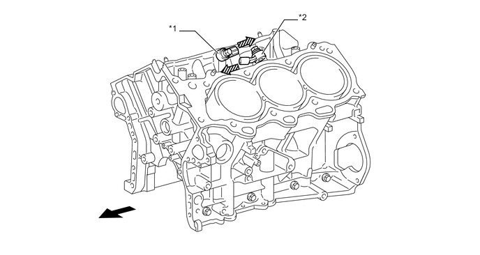
Text in Illustration *1 Knock Control Sensor (KNK1) *2 Knock Control Sensor (KNK2) Engine Front 
Knock Control Sensor Mounting Direction
-
-
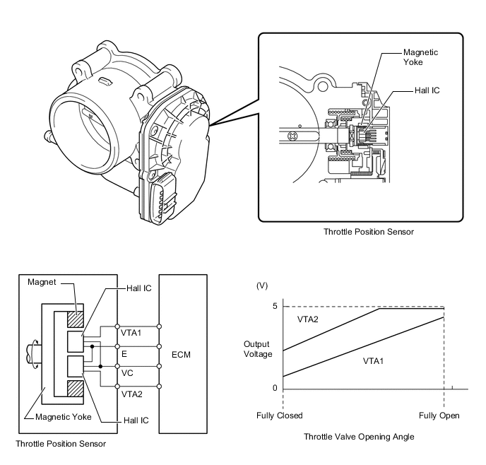
Throttle Position Sensor
-
A non-contact type throttle position sensor is used. This sensor uses a Hall IC, which is mounted on the throttle body.
-
The Hall IC is surrounded by a magnetic yoke. The Hall IC converts the changes that occur in the magnetic flux into electrical signals and outputs them as throttle valve effort to the ECM.
-
The Hall IC contains circuits for the main and sub signals. It converts the throttle valve opening angles into electric signals with two differing characteristics and outputs them to the ECM.
-
-
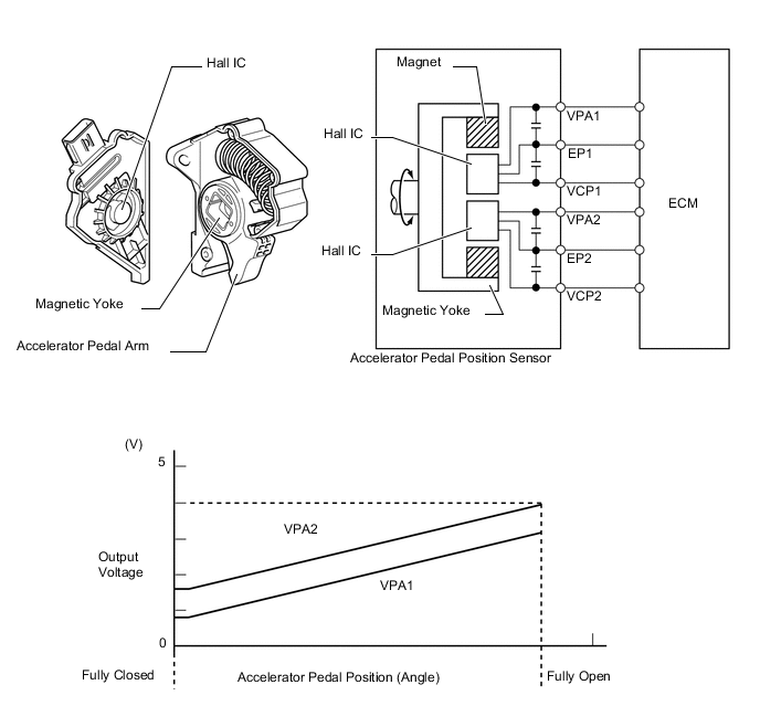
Accelerator Pedal Position Sensor
-
This non-contact type accelerator pedal position sensor uses a Hall IC, which is mounted on the accelerator pedal arm.
-
A magnetic yoke is mounted at the base of the accelerator pedal arm. This yoke rotates around the Hall IC in accordance with the amount of effort that is applied to the accelerator pedal. The Hall IC converts the changes in the magnetic flux that occur into electrical signals, and outputs them in the form of accelerator pedal position signals to the ECM.
-
This accelerator pedal position sensor includes 2 Hall ICs and circuits for the main and sub signals. It converts the accelerator pedal depressed angles into electric signals with two differing characteristics and outputs them to the ECM.
-
-
Camshaft Timing Oil Control Valve Assembly
-
This camshaft timing oil control valve assembly controls the spool valve using duty cycle control from the ECM. This allows hydraulic pressure to be applied to the VVT-i controller advanced or retarded side. When the engine is stopped, the camshaft timing oil control valve assembly is in the most retarded position.
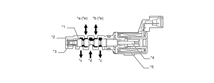
Text in Illustration *1 Spool Valve *2 Sleeve *3 Spring *4 Plunger *5 Coil - - *a To VVT-i Controller (Advance Side) *b To VVT-i Controller (Retard Side) *c Drain *d Oil Pressure *e On the camshaft timing oil control valve assembly (exhaust), the advance and retard sides are reversed. - -
-
-
Throttle Control Motor
-
A DC motor with excellent response and minimal power consumption is used for the throttle control motor. The ECM performs the duty cycle control of the direction and the amperage of the current that flows to the throttle control motor in order to regulate the opening of the throttle valve.
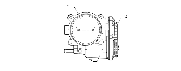
Text in Illustration *1 Throttle Valve *2 Throttle Position Sensor Portion *3 Throttle Control Motor - -
-
-
Ignition Coil Assembly
-
The Direct Ignition System (DIS) provides 6 ignition coil assemblies, one for each cylinder. The spark plug caps, which provide contact to spark plugs, are integrated with the ignition coil. Also, an igniter is enclosed to simplify the system.
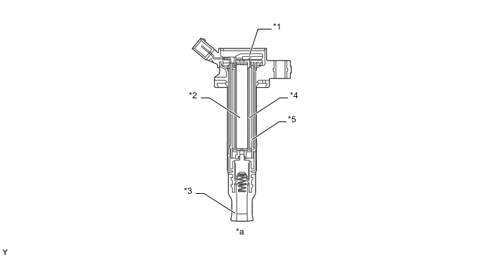
Text in Illustration *1 Igniter *2 Iron Core *3 Plug Cap *4 Secondary Coil *5 Primary Coil - - *a Ignition Coil Cross Section - -
-
-
Spark Plug
-
Long-reach type spark plugs are used. This type of spark plug allows the area of the cylinder head that receives the spark plugs to be made thick. Thus, the water jacket can be extended near the combustion chamber, which contributes to cooling performance.
-
Iridium-tipped spark plugs are used to achieve a 192000 km (120000 miles) maintenance interval. By making the center electrode of iridium, it is possible to achieve superior ignition performance and durability when compared to platinum-tipped spark plugs.
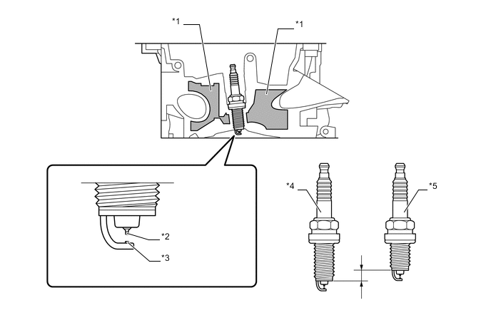
Text in Illustration *1 Water Jacket *2 Iridium Tip *3 Platinum Tip *4 Long-reach Type Spark Plug *5 Conventional Type Spark Plug - -
-
-
-
OPERATION
-
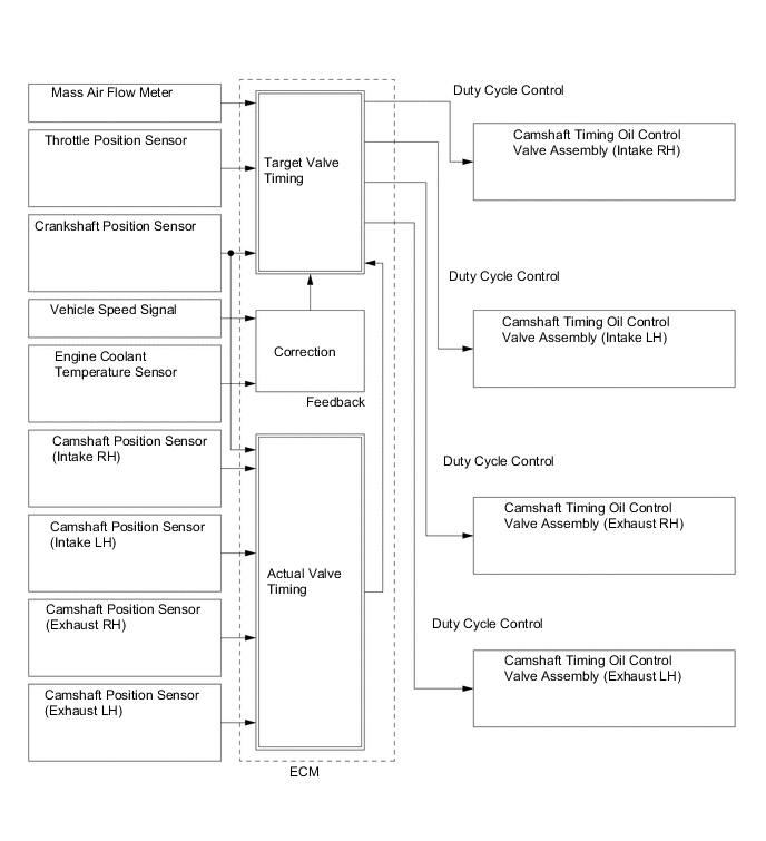
Dual VVT-i System
-
Using the engine speed, intake air mass, throttle position and engine coolant temperature, the ECM can calculate optimal valve timing for each driving condition and controls the camshaft timing oil control valve. In addition, the ECM uses signals from the camshaft position sensor and the crankshaft position sensor to detect the actual valve timing, thus providing feedback control to achieve the target valve timing.
-
When the camshaft timing oil control valve is positioned as illustrated below by the advance signals from the ECM, the resultant oil pressure is applied to the timing advance side vane chamber to rotate the camshaft in the timing advance direction:
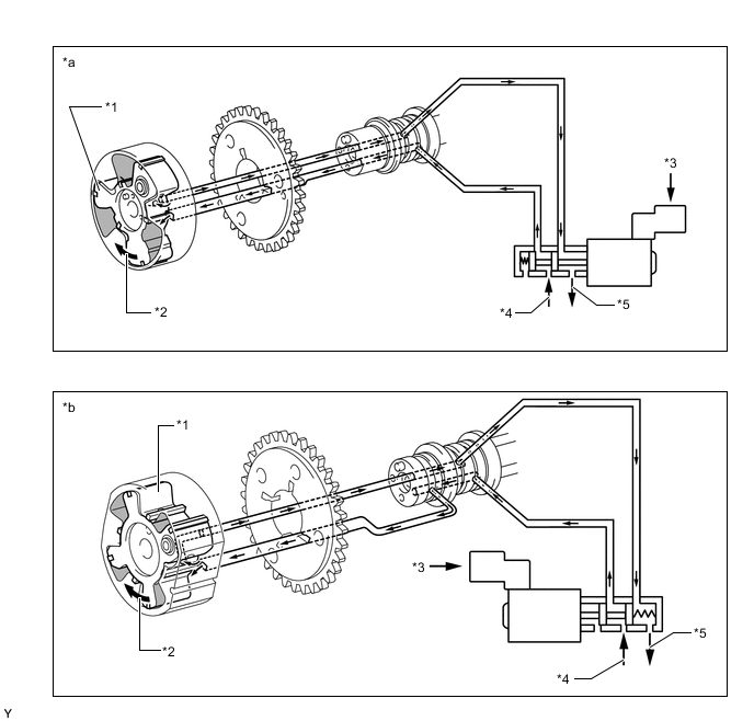
Text in Illustration *1 Vane *2 Rotation Direction *3 ECM *4 In (Oil Pressure) *5 Drain (Oil Pressure) - - *a Advance Side Operation Intake Side *b Advance Side Operation Exhaust Side -
When the camshaft timing oil control valve is positioned as illustrated below by the retard signals from the ECM, the resultant oil pressure is applied to the timing retard side vane chamber to rotate the camshaft in the timing retard direction:
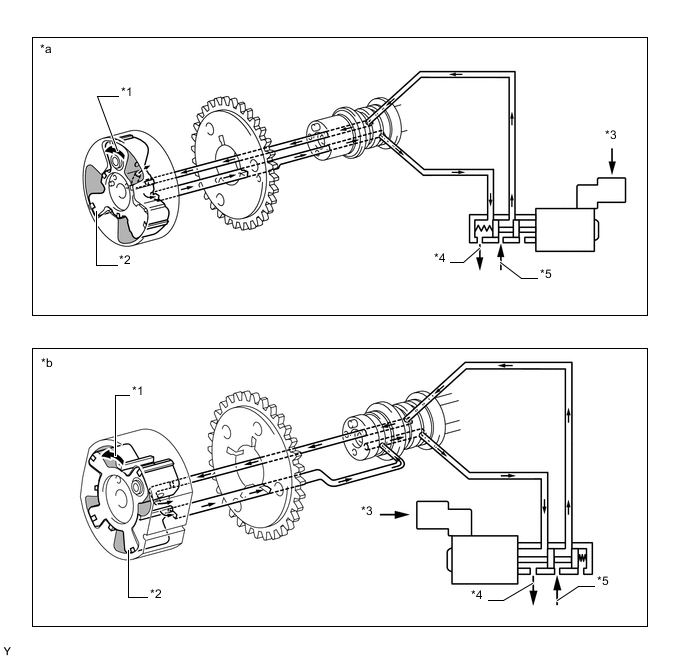
Text in Illustration *1 Rotation Direction *2 Vane *3 ECM *4 Drain (Oil Pressure) *5 In (Oil Pressure) - - *a Retard Side Operation Intake Side *b Retard Side Operation Exhaust Side -
After reaching the target timing, the engine valve timing is maintained by keeping the camshaft timing oil control valve in the neutral position unless the engine operating conditions change. This maintains the engine valve timing at the desired target position by preventing the engine oil from running out of the oil control valve.
-
-
Fuel Pump Control
-
In this vehicle, there are 2 types of fuel pump controls. The fuel pump is controlled to an optimum speed to match the engine operating conditions, and the fuel pump operation is stopped when the SRS airbags deploy.
-
The ECM transmits a fuel pump operation request signal to the fuel pump control ECU that corresponds to the engine operating conditions. The fuel pump control ECU receives this request signal and controls the speed of the fuel pump in 3 stages. As a result, under light engine loads, fuel pump speed is kept low to reduce electric power loss.
-
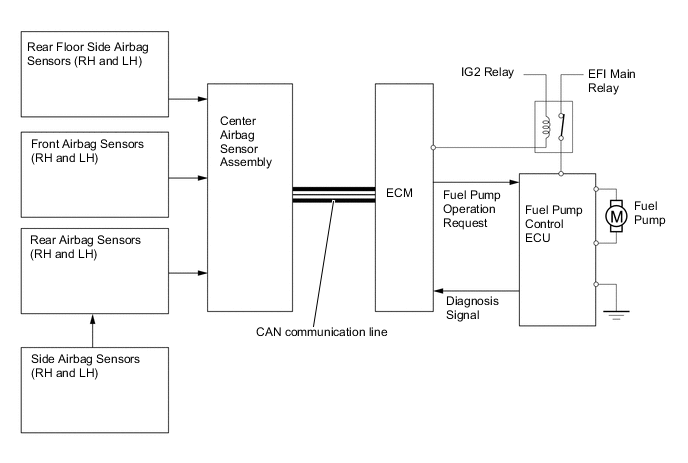
A fuel cut control is used to stop the fuel pump when any of the SRS airbags deploys. In this control, if an airbag deployment signal from the center airbag sensor assembly is detected by the ECM, the ECM will turn off the circuit opening relay. As a result, the power supply to the fuel pump control ECU is stopped, causing the fuel pump to stop operating. After the fuel cut control has been activated, turning the ignition switch from off to ON cancels the fuel cut control, and the engine can be restarted.
-
The fuel pump control ECU controls fuel pump speed by receiving a duty cycle signal (FPC terminal input) from the ECM, and control is performed in 3 stages.
-
The fuel pump control ECU also detects failures in the input and output circuits at the fuel pump ECU and transmits the failure status to the ECM.
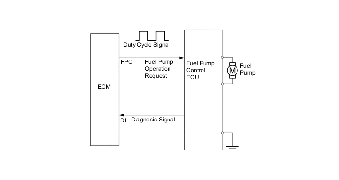
FPC Terminal Input FPC Input Signal (Duty Cycle Signal) Fuel Pump Speed 
High 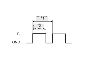
*1 12.3 ms *2 8.2 ms Middle 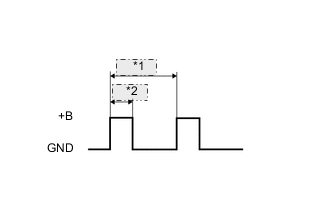
*1 12.3 ms *2 4.1 ms Low 
Stop
-
-
ETCS-i
-
The ECM drives the throttle control motor by determining the target throttle valve opening in accordance with the respective operating condition.
-
The ECM controls the throttle to an optimal throttle valve opening that is appropriate for the driving conditions such as the amount of accelerator pedal effort and the engine speed in order to achieve excellent throttle control and comfort in all operating ranges.
-
The ECM controls the throttle valve in order to constantly maintain an ideal idle speed.
-
As part of the TRC, the throttle valve opening angle is reduced by a demand signal sent from the skid control ECU to the ECM. This demand signal is sent if an excessive amount of slippage occurs at a drive wheel, thus ensuring vehicle stability and applying an appropriate amount of power to the road.
-
In order to bring the effectiveness of the VSC into full play, the throttle valve angle is regulated through a coordination control by the skid control ECU and the ECM.
-
On the models with cruise control system, the ECM directly actuates the throttle valve for operation of the cruise control.
-
On the models with dynamic radar cruise control system, the dynamic radar cruise control uses a millimeter wave radar sensor and driving support ECU to determine the distance, direction, and relative speed of a vehicle ahead. Thus, the system can effect deceleration control, follow-up control, constant speed control, and acceleration control. To make these controls possible, the ECM controls the throttle valve.
-
-
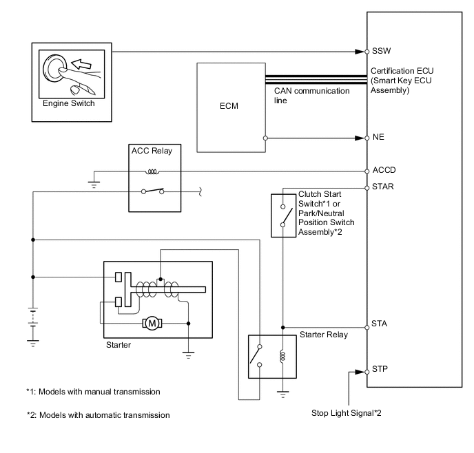
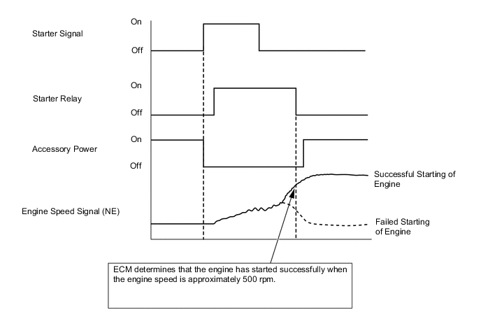
Starter Control
-
When the driver pushes the engine switch once and the certification ECU (smart Key ECU assembly) detects a start signal, the certification ECU (smart Key ECU assembly) will output ACCD and STAR signals and begin cranking. Also, the driver can continue cranking for up to 30 seconds by pushing and holding the engine switch.
-
If the engine speed reaches approximately 500 rpm, the ECM will judge that the engine has started and will send a signal to the certification ECU (smart Key ECU assembly) using CAN communication. The certification ECU (smart Key ECU assembly) will then stop the operation of the starter.
-
If CAN communication is cut between the certification ECU (smart Key ECU assembly) and the ECM, the certification ECU (smart Key ECU assembly) will receive an engine speed signal (NE) directly from the ECM and will stop the operation of the starter.
-
This system will cut off the power current which activates the accessories while the engine is being cranked. This prevents the intermittent blinking of the accessory lights caused by the voltage instability that occurs during engine cranking.
-
This system has the following protections:
-
The starter will not operate if the engine is operating normally.
-
If the engine switch is pushed and held, cranking will stop once the engine speed reaches a pre-determined level. This prevents the starter from over-revving.
-
If the engine does not start even after approximately 6 seconds of starter operation, the certification ECU (smart Key ECU assembly) will cancel the starter relay output. Furthermore, if the engine does not start after the engine switch has been pushed and held and cranking has continued for 30 seconds, cranking will be canceled in order to protect the starter.
-
It will not be possible to operate the starter for 2 seconds after engine starting has failed and cranking has been canceled. This helps to protect the starter.
-
-
-