BODY STRUCTURE
-
CONSTRUCTION
-
Body Shell
-
High-tensile strength steel, ultra high-tensile strength steel, hot-stamped steel and aluminum are used in order to achieve excellent body rigidity and a lightweight body.
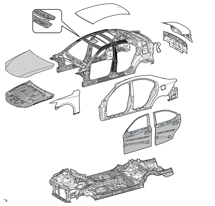

Ultra High-tensile Strength Steel 
High-tensile Strength Steel 
Aluminum 
Hot-stamped Steel
-
-
Roof
-
Along with the use of high-tensile strength sheet steel, the inner windshield header panel is structured with closed cross-sections, thus ensuring superior roof strength.
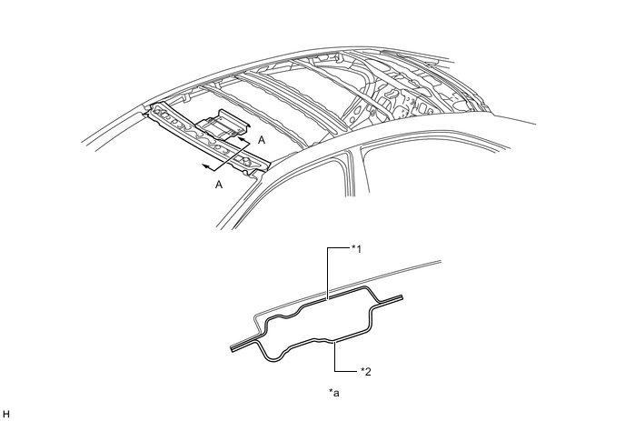
*1 Outer Windshield Header Panel *2 Inner Windshield Header Panel *a A-A Cross Section - -
-
-
Front Fender
-
An upper front pillar door opening gusset, which connects the apron member portion and the front pillar portion, is provided in the front fender portion. As a result, a superior steering feel and roll feeling are ensured. In addition, to avoid a reduction in collision safety, a bead shape is provided to allow for a structure which is easily deform able in a collision.
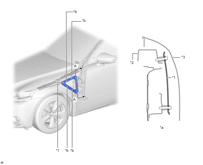
*1 Upper Front Pillar Door Opening Gusset *2 Inner Cowl Top Side Panel *3 Front Fender Panel - - *a A-A Cross Section *b Bead
-
-
Floor Pan
-
The No. 3 center floor reinforcement is located so as to connect the right and left of the front side installation portion of the rear suspension member sub-assembly in a straight line, thus ensuring a high level of rigidity at the load point. As a result, superior maneuvering stability has been achieved.
-
Spot welding points between the front center floor pan and center floor pan, the No. 2 center floor cross member and center floor pan and the No. 1 rear floor cross member and center floor pan are optimally positioned, thus achieving superior maneuvering stability.
-
The thickness of the center floor pan has been increased, thus achieving superior maneuvering stability, riding comfort and quietness.
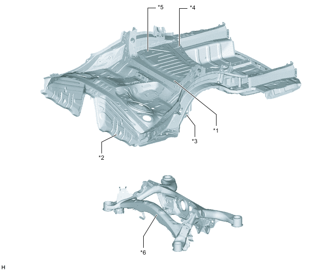
*1 Center Floor Pan *2 No. 2 Center Floor Cross Member *3 Front Center Floor Pan *4 No. 3 Center Floor Reinforcement *5 No. 1 Rear Floor Cross Member *6 Rear Suspension Member Sub-assembly
-
-
Floor Brace
-
The shapes of the radiator support sub-assembly and rear under body have been optimized and each type of brace provided on the under floor has been optimally placed, thus ensuring superior maneuvering stability.
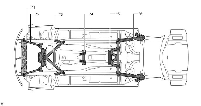
*1 Radiator Support Sub-assembly *2 Upper No. 2 Front Suspension Member *3 Front Suspension Member Brace *4 Engine Under Brace Sub-assembly *5 Center Front Floor Brace *6 Rear Body Mounting Cushion Sub-assembly
-
-