BODY STRUCTURE
-
FUNCTION
-
Front Wheel Opening Extension Pad
-
A step shape is used for the lower end of the front wheel opening extension pad, thus aiming for optimization of aerodynamic performance. The outer side step of the front wheel opening extension pad has been extended in its lower end position, thus suppressing the volume of air hitting against the rotating bodies of the tires. As a result, turbulence generated by the rotation of the front tires which disturbs airflow around the front tires has been suppressed, thus reducing air resistance and ensuring a high level of straight-line stability at high speed by adjusting the airflow. In addition, the inner side step of the front wheel opening extension pad has been shortened in its lower end portion, thus aiming for prevention of the front wheel opening extension pad itself from causing air resistance.
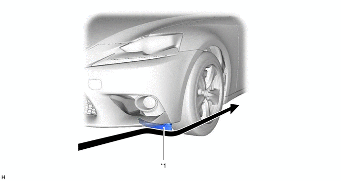
*1 Front Wheel Opening Extension Pad - - 
Airflow - -
-
-
Front Fender Liner
-
A groove is provided in the front fender liner. As a result, airflow in the wheelhouse is introduced to smoothly flow parallel to the tires to make it flow in the wheelhouse smoothly, thus ensuring superior maneuver stability.
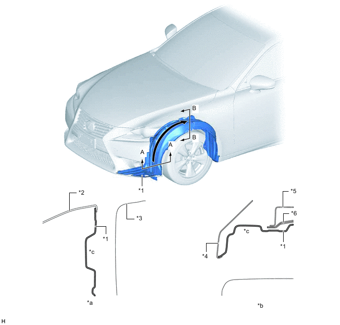
*1 Front Fender Liner *2 Front Bumper Cover *3 Front Tire *4 Front Fender Panel *5 Upper Front Apron to Cowl Side Member *6 Front Spring Support *a A-A Cross Section *b B-B Cross Section *c Groove Structure - - Airflow - -
-
-
Rear Floor Housing Shield
-
A rear floor housing shield is provided, with the aim of suppressing the air volume hitting against the rotating bodies of the tires. As a result, turbulence generated by the rotation of the rear tires, which disturbs airflow around the rear tires has been suppressed, thus reducing air resistance and ensuring a high level of straight-line stability at high speed by adjusting the airflow.
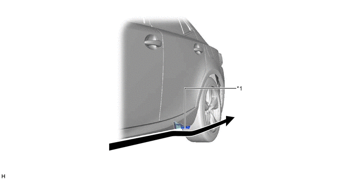
*1 Rear Floor Housing Shield - - Airflow - -
-
-
Rear Wheel House Liner
-
Beads are provided to free the high-pressure turbulence outward that causes air resistance in the rear wheelhouse by the rotation of the rear tires.
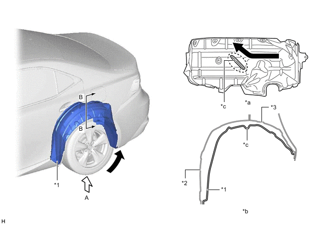
*1 Rear Wheel House Liner *2 Inner Quarter Wheel House Panel *3 Outer Quarter Wheel House Panel - - *a View from A *b B-B Cross Section *c Bead - - Airflow - -
-
-
Luggage Compartment Door
-
The rear end portion of the luggage compartment door panel sub-assembly has been given a sharp shape, thus aiming for air resistance reduction by smoothly introducing airflow from the roof to the rear.
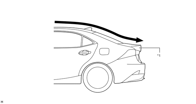
*1 Luggage Compartment Door Panel Sub-assembly - - Airflow - -
-
-
Aero Stabilizing Fin
-
An aero stabilizing fin is provided on the front pillar base and the rear combination light lens for enhanced aerodynamics.
-
After passing the aero stabilizing fin, the air speed will increase and vortex flow will be generated.
-
This vortex flow increases the speed of surrounding air while at the same time pulling the airflow towards the vehicle body.
-
The airflow with higher speed passes near both sides of the vehicle body and ends at the rear of the vehicle. This helps to hold the vehicle body, and thus stabilizes the vehicle.
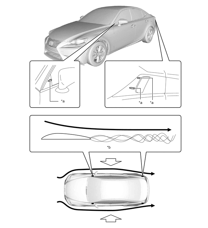
*a Aero Stabilizing Fin *b Vortex Airflow 
Hold the Vehicle from Both Sides
-
-
-
Under Body
-
To create a smooth rearward airflow for the air which enters from the front to under floor, the following parts with airflow adjustment effects are located on the lower surface of the vehicle. Smooth airflow in the lower surface of the vehicle enhances the speed of airflow and a low pressure region is created between the vehicle and the road surface (Venturi effect). This low pressure region attracts the vehicle to the road surface, thus causing down force. Thus, superior straight-line stability has been achieved.
-
A flat airflow adjustment surface is provided for the engine under cover. Also, an aero stabilizing fin is provided.
-
The surface area of the front floor cover and the No. 1 rear floor board sub-assembly has been increased, and the height from the ground has also been optimized. In addition, an aero stabilizing fin is provided.
-
The under floor cutting angle of the No. 1 floor under cover has been optimized. In addition, an aero stabilizing fin is provided.
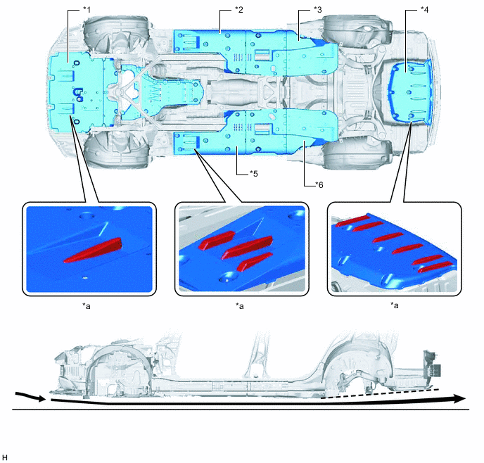
*1 Engine Under Cover *2 Front Floor Cover LH *3 No. 1 Floor Under Cover *4 No. 1 Rear Floor Board Sub-assembly *5 Front Floor Cover RH *6 No. 2 Floor Under Cover *a Aero Stabilizing Fin - - Airflow - - -
-
-