BODY STRUCTURE
-
FUNCTION
-
Impact Absorbing Structure for Frontal Collision
-
A structure that ensures collision energy absorption efficiency, dissipates impact, and minimizes cabin deformation during a frontal collision has been achieved.
-
Ultra high-tensile strength sheet steel (980 MPa class) is used for the No. 1 rocker panel reinforcement. In addition, strengthening reinforcement is added in the No. 1 rocker panel reinforcement. As a result, deformation of the cabin, which is caused by the vehicle's pitching in an offset front collision, has been suppressed.
-
The rocker front end portion (outer rocker extension) is protruded forward to receive collision load input from the tires in an offset front collision and to absorb the impact, thus suppressing body deformation on the periphery of the cabin.
-
The lower front body pillar reinforcement and outer front body pillar reinforcement are constructed with an overlap structure that features upper-and-lower separation together to strengthen the front body pillar portion, thus suppressing body deformation (caused by collision load input from the tires in an offset front collision) on the periphery of the cabin.
-
High-tensile strength sheet steel (590 MPa class) is used for the front door inside panel reinforcement. In addition, the longitudinal wall of the front door inside panel reinforcement is located further toward the interior side than the centroid, thus suppressing deformation of the door by compression load in an offset front collision.
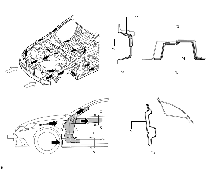
*1 No. 1 Rocker Panel Reinforcement *2 No. 4 Rocker Panel Reinforcement *3 Outer Front Body Pillar Extension *4 Lower Front Body Pillar Reinforcement *5 Front Door Inside Panel Reinforcement - - *a A-A Cross Section *b B-B Cross Section *c C-C Cross Section - - 
Impact 
Path to Collision Energy -
-
-
Impact Absorbing Structure for Side Collision
-
A structure that ensures collision energy absorption efficiency, dissipates impact, and minimizes cabin deformation during a side collision has been achieved.
-
Hot-stamped steel (1500 MPa class), ultra high-tensile strength sheet steel (980 MPa class) and high-tensile strength sheet steel (590 MPa class) are used for each body frame part, thus ensuring strength against side collisions and achieving weight reduction and structure simplicity.
Tech Tips
Hot-stamped steel is a highly strengthened material, which is made by forming and cooling heated steel simultaneously and then hardening it.
-
Hot-stamped steel (1500 MPa class) is used for the upper center body pillar reinforcement. In addition, the high-tensile strength sheet steel (590 MPa class) center pillar upper hinge reinforcement is located inside the upper center body pillar reinforcement.
-
Hot-stamped steel (1500 MPa class) is used for the roof side rail.
-
High-tensile strength sheet steel (590 MPa class) is used for the center roof panel reinforcement.
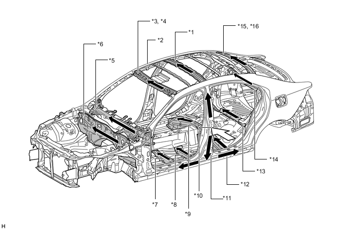
*1 Center Roof Panel Reinforcement *2 Roof Side Rail *3 Outer Windshield Header Panel *4 Inner Windshield Header Panel *5 Instrument Panel Reinforcement Assembly *6 Dash Panel Sub-assembly *7 Front Floor Cross Member *8 Front Floor Cross Side Member *9 Center Floor Cross Member *10 Upper Center Body Pillar Reinforcement *11 Center Pillar Upper Hinge Reinforcement *12 Outer Rocker Panel *13 Rear Center Floor Cross Member Sub-assembly *14 Room Partition Panel Sub-assembly *15 Upper Inner Back Window Frame *16 Back Window Frame Impact Path to Collision Energy -
Ultra high-tensile strength sheet steel (980 MPa class) is used for the No. 1 rocker panel reinforcement, and high-tensile strength sheet steel (590 MPa class) is used for the outer rocker panel and No. 1 rocker panel reinforcement, which are inside the No. 1 rocker panel reinforcement. Front-and-rear length has been increased to suppress corruption of the rocker cross-section in a side collision, thus reducing the center body pillar's intrusion into the cabin.
-
The thickness of the rear door side impact protection beam has been increased, thus reducing the rear door's intrusion into the cabin in a side collision.
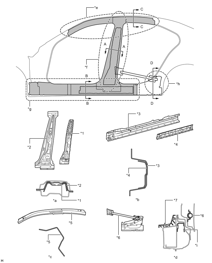
*1 Center Pillar Upper Hinge Reinforcement *2 Upper Center Body Pillar Reinforcement *3 Outer Rocker Panel *4 No. 1 Rocker Panel Reinforcement *5 Roof Side Rail *6 Rear Door Side Impact Protection Beam *7 Inner Rear Rocker Panel Protector - - *a A-A Cross Section *b B-B Cross Section *c C-C Cross Section *d D-D Cross Section *e Roof Side Rail Portion *f Center Body Pillar Portion *g Rocker Portion *h Rear Rocker Portion *i Bulkhead - -
-
Collision load input from the center body pillar in a side collision is transferred either to the ECU bracket installed on the center front floor panel tunnel sub-assembly or its upper portion through the front floor cross member reinforcement sub-assembly, separate type front seat cushion pad and connecting rod. As a result, the diffusion of collision load has been optimized to reduce the deformation amount of the body in a side collision.
-
The center roof panel reinforcement (high-tensile strength steel (590 MPa class)) and No. 2 roof panel reinforcement bracket are located on the upper portion of the center pillar on models with normal roof, to suppress the amount of side rail intrusion by transferring and scattering the load to the side opposite to the collision, thus aiming for a reduction in the amount of body deformation in a side collision.
-
A front door stiffener cushion is provided inside the door panel to enhance the transmission efficiency of collision load, thus aiming for a reduction of the injury criterion level.
-
The lower front door trim pad is provided in the front door trim board sub-assembly to reduce collision load toward the passengers in a side collision, thus aiming for a reduction of the injury criterion level.
-
The position, shape and rigidity of the front door trim board sub-assembly shoulder portion and the front door armrest assembly have been optimized to reduce collision load toward the driver and front passengers in a side collision, thus aiming for a reduction of the injury criterion level.
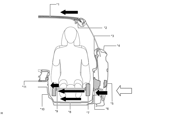
*1 Center Roof Panel Reinforcement *2 No. 2 Roof Panel Reinforcement Bracket *3 Front Door Trim Board Sub-assembly *4 Front Door Outside Panel *5 Front Door Stiffener Cushion *6 Lower Front Door Trim Pad *7 Separate Type Front Seat Cushion Pad *8 Front Floor Cross Member Reinforcement Sub-assembly *9 Connecting Rod *10 Center Front Floor Panel Tunnel Sub-assembly *11 ECU Bracket - - Impact Path of Collision Energy -
-
-
Impact Absorbing Structure for Rear Collision
-
The use of braces placed in the optimum position both above and below the hybrid battery prevents deformation during a rear collision and protects the hybrid battery.
-
Reinforcing material is used and floor pan shape has been cleverly designed in consideration of the space for the hybrid battery, achieving a spacious luggage compartment.
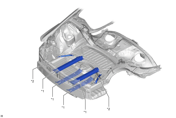
*1 Rear Floor Panel Brace *2 No.2 Rear Floor Panel Brace
-
-
Lessening Pedestrian Injury
-
A body that lessens injury to pedestrians in the event of a collision is used in consideration of reducing pedestrian injuries. The energy-absorbing structure is used around the front fender, hood panel, cowl top panel and front bumper, absorbing impact energy to a pedestrians head and legs.
-
A pop up hood has been adpted in consideration of reducing pedestrian injuries due to impact against the engine hood panel in the event of a collision. The adoption of pop up hood ensures a sporty form and pedestrian protection.
-
Pop Up Hood
-
If the front bumper collides with an object, a pedestrian detection chamber assembly in the front bumper cover receives impact energy. The pressure sensors (pedestrian protection sensor RH/LH) detect the collision and send a collision signal to the airbag sensor assembly.
-
The airbag sensor assembly determines if a collision has occurred based on the signal from the pressure sensors (pedestrian protection sensor RH/LH) and sends an ignition signal to the pop up hood lifter assembly installed under the hood hinge.
-
On receiving the ignition signal from the airbag sensor assembly, the pop up hood lifter assembly pushes the piston upwards, causing the rear of the hood to be rapidly lifted to make clearance between the hood panel and the upper part of the engine. This helps reduce the impact to a pedestrian, such as to the head.
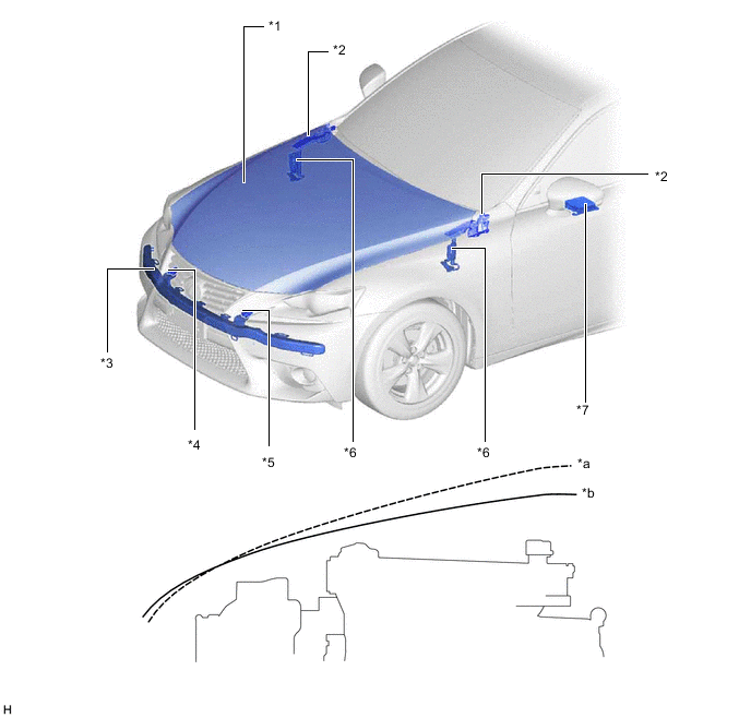
*1 Hood Panel *2 Hood Hinge *3 Pedestrian Detection Chamber Assembly *4 Pedestrian Detection Sensor RH *5 Pedestrian Detection Sensor LH *6 Pop Up Hood Lifter Assembly *7 Airbag Sensor Assembly - - *a Popped Up *b Not Popped Up -
Hood Panel
-
A vertical bead structure is used for the inner hood panel, thus aiming for a reduction of impact against the pedestrian's head, etc. in a collision with a pedestrian. In addition, the height and pitch of the beads have been optimized, thus achieving a slim hood sub-assembly structure while maintaining impact reduction performance.
-
Bead shapes which can form bending base points are provided at the end of the inner hood panel. As a result, the structure bends to deform easily at the base points created by the ledge end of the inner hood panel and the beads next to the hood lock hook base when the pedestrian's thigh area collides with the hood end, thus aiming for a reduction of impact against the pedestrian's thigh area.
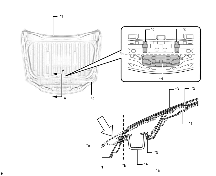
*1 Inner Hood Panel *2 Hood Panel Reinforcement *3 Hood Panel *4 Hood Lock Hook *5 Hood Lock Hook Base - - *a A-A Cross Section *b Fold Line *c Bead *d Ledge *e Before Collision *f After Impact Absorption Impact - - -
Front Fender
-
A structure which is easily bent is used for the upper front fender protector. If a pedestrian's head, etc. collides with the hood sub-assembly, the upper front fender protector bends to reduce opposed reaction force from the hood sub-assembly to the head etc., thus aiming for a reduction of impact against a pedestrian.
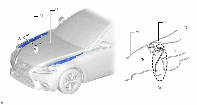
*1 Upper Front Fender Protector *2 Hood Sub-assembly *3 Front Fender Panel *4 Hood Panel *5 Inner Hood Panel - - *a A-A Cross Section *b Structure which can be Easily Bent -
Cowl Top Panel
-
By providing fold points on the front outer cowl top panel and by making the structure easily crushable, energy coming from the expected direction in a head area collision is more effectively absorbed, and a structure which reduces the remaining areas which are not completely crushed has been achieved. As a result, impact against the head area, etc. is reduced in a collision with a pedestrian.
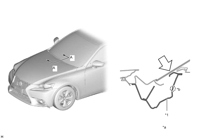
*1 Front Outer Cowl Top Panel - - *a A-A Cross Section *b After Collision Impact - -
-
-
-