AIR CONDITIONING SYSTEM
-
OPERATION
-
Mode Position and Door Operation
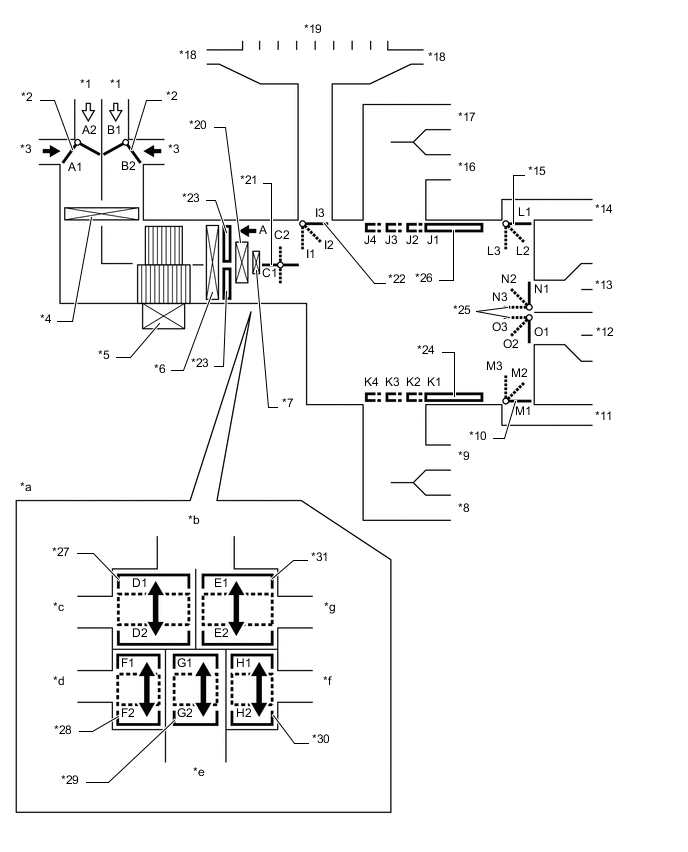
*1 Recirculated Air *2 Air Inlet Control Door *3 Fresh Air *4 Air Refiner Element *5 Blower with Fan Motor Sub-assembly *6 No. 1 Cooler Evaporator Sub-assembly *7 Quick Heater Assembly *8 Side Register (Front Passenger Side) *9 Center Register (Front Passenger Side) *10 Mode Control Door (for Front Passenger Footwell Register) *11 Front Footwell Register Duct (Front Passenger Side) *12 Rear Footwell Register Duct *13 Console Box Register *14 Front Footwell Register Duct (Driver Side) *15 Mode Control Door (for Driver Footwell Register) *16 Center Register (Driver Side) *17 Side Register (Driver Side) *18 Side Defroster *19 Center Defroster *20 No. 1 Heater Radiator Unit Sub-assembly *21 Inside-and-outside Dual Air Layer Control Door *22 Mode Control Door (for Defroster) *23 Air Mix Control Door *24 Mode Control Door (for Front Passenger Center and Side Register) *25 Mode Control Door (for Console Box Register and Rear Passenger Footwell Register Duct) *26 Mode Control Door (for Driver Center and Side Register) *27 Air Mix Control Door (for Driver Side Upper Layer) *28 Air Mix Control Door (for Driver Side Lower Layer) *29 Air Mix Control Door (for Rear Passenger) *30 Air Mix Control Door (for Front Passenger Lower Layer) *31 Air Mix Control Door (for Front Passenger Side Upper Layer) - - *a View from A *b To Center and Side Defrosters *c To Driver Side Center and Side Registers *d To Driver Side Footwell Register Duct *e To Console Box Register and Rear Footwell Register Duct *f To Front Passenger Side Footwell Register Duct *g To Front Passenger Side Center and Side Register - - Mode Position and Door Operation Control Door Operation Position Damper Position Operation Air Inlet Control Door FRESH A2, B1 Brings in fresh air. Dual Air Layer (Auto Control) A1, B1 - B2 The upper layer is used to automatically regulate the position between the fresh and recirculation mode in response to the control conditions. The lower layer is used to recirculate internal air. RECIRCULATION A1, B2 Recirculates internal air. Inside-and-outside Dual Air Layer Control Door Dual Air Layer (Auto Control) C1 - C2 Separates or integrates the upper layer and lower layer in response to the control conditions to control the inside-and-outside dual air layers. Air Mix Control Door MAX COLD to MAX HOT Temperature Setting D1 - D2 For front passenger side register E1 - E2 For driver side register F1 - F2 For front passenger side front footwell register G1 - G2 For rear registers and rear heater ducts. This door operates in accordance with door operation for the driver side front footwell register (H1-H2). H1 - H2 For driver side front footwell register Mode Control Door 
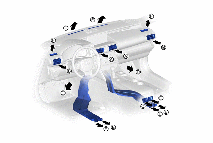
FACE J1, K1, L1, M1, N3, O1, I3 Air blows out of the front center register, side register and console box register. 
BI-LEVEL J2, K2, L2, M2, N2, O2, I3 Air blows out of the front center register, side register, console box register and front and rear footwell register ducts. Air may blow out from the center defroster and side defroster depending on the cabin environment (I2). 
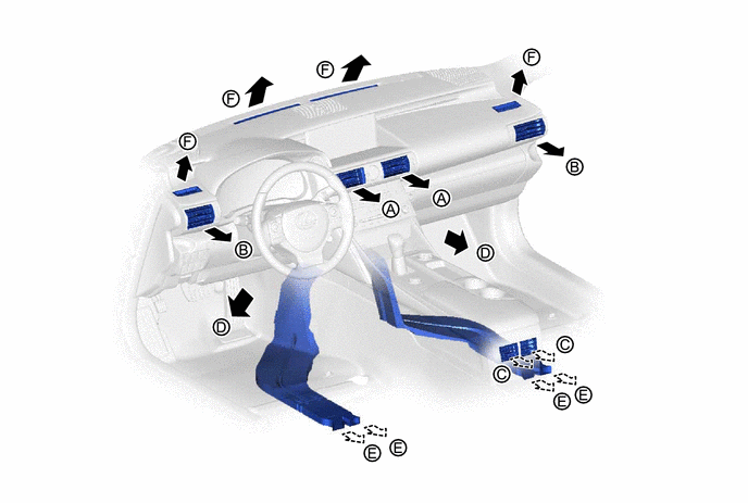
FOOT J3, K3, L3, M3, N2, O3, I2 Air blows out of the front footwell register and rear footwell register ducts. In addition, air blows out slightly from the front center register, side register and console box register. 
FOOT AND DEFROSTER J3, K3, L2, M2, N2, O2, I1 Defrosts the windshield through the center defroster and side defroster, while air is also blown out from the front footwell register and rear footwell register ducts. In addition, air blows out slightly from the front center register, side register and console box register. 
DEFROSTER J4, K4, L1, M1, N1, O1, I1 Defrosts the windshield through the center defroster and side defroster ducts. -
Air Outlets and Airflow Volume (for All Seat Control Modes)
Mode Selection Face Footwell Defroster Auto Manual Center Side Rear Front Rear F A B C D E FACE-U*1

- 
- - - FACE-L*1
- 
- FACE-R*1, *2

- - - BI-LEVEL*1, *2
- FOOT-D*1
- FOOT-R*1, *2
FOOT-F*1
- FOOT AND DEFROSTER *1, *2
DEFROSTER *1, *2
- - - - - Tech Tips
The size of the circle ○ indicates the proportion of air flow volume.
*1: When each mode is turned on by automatic control. In addition, -U, -L and -R in FACE mode are selected by the automatic control and -D, -R or -F in FOOT mode as well.
*2: When each mode is selected by a manual operation.
*3: Air may blow out from the defroster in response to the cabin temperature and moisture, and outside temperature conditions.
-
Air Outlets and Airflow Volume (for Front Seat Control Modes)
Indication Selection Face Footwell Defroster Auto Manual Center Side Rear Front Rear F A B C D E FACE-U*1
- - - - - FACE-L*1
- - - - FACE-R*1, *2
- - - - BI-LEVEL*1, *2
- - *3
FOOT-D*1
- - - FOOT-R*2
- - FOOT-F*1
- - FOOT AND DEFROSTER *1, *2
- - DEFROSTER *1, *2
- - - - - Tech Tips
The size of the circle ○ indicates the proportion of air flow volume.
*1: When each mode is turned on by automatic control. In addition, -U, -L and -R in FACE MODE are selected by the automatic control and -D, -R or -F in FOOT MODE as well.
*2: When each mode is selected by a manual operation.
*3: Air may blow out from the defroster in response to the cabin temperature and moisture, and outside temperature conditions.
-