AIR CONDITIONING SYSTEM
-
CONSTRUCTION
-
Compressor with Motor Assembly
-
Along with the installation of the hybrid system, an ES27 type electric inverter compressor that is driven by a motor is used. The basic construction and operation of this compressor is the same as an ordinary scroll compressor, except that it is driven by an electric motor.
-
The A/C inverter is integrated with the compressor.
-
The electric motor is actuated by 3-phase alternating current created from the direct current (230.4 V) supplied to the A/C inverter. As a result, the air conditioning system is actuated without depending on the operation of the engine, thus realizing a comfortable air conditioning system and low fuel consumption.
-
Due to the use of an electric inverter compressor, the compressor speed can be controlled at the required speed calculated by the air conditioning amplifier assembly. Thus, the cooling and dehumidification performance and power consumption have been optimized.
-
Low-moisture permeation hoses are used for the suction and discharge hoses at the compressor in order to minimize the entry of moisture into the refrigeration cycle.
-
The compressor is supplied with high-voltage direct current, and uses high-voltage alternating current internally. If an open or short circuit occurs in the compressor, the hybrid vehicle control ECU will cut off the A/C inverter circuit.
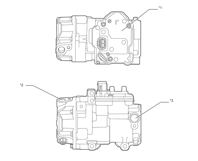
*1 A/C Inverter *2 Discharge Hose Port *3 Suction Hose Port - - -
The electric inverter compressor consists of a spirally wound fixed scroll and variable scroll that form a pair, a brushless motor, an oil separator, a motor shaft and an A/C inverter.
-
The fixed scroll is integrated with the housing. Because the rotation of the shaft causes the variable scroll to revolve while maintaining the same posture, the volume of the space that is partitioned by both scrolls varies to perform the suction, compression, and the discharge of the refrigerant gas.
-
Locating the suction port directly above the scrolls enables direct suction, thus realizing improved suction efficiency.
-
Containing a built-in oil separator, this compressor is able to separate the compressor oil that is intermixed with the refrigerant and circulates in the refrigeration cycle, thus realizing a reduction in the oil circulation rate.
-
This inverter converts the HV battery nominal voltage of DC 230.4 V into AC and supplies power to operate the compressor.
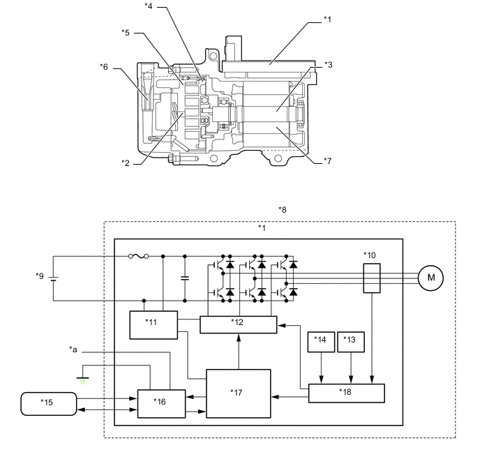
*1 A/C Inverter *2 Discharge Port *3 Motor Shaft *4 Variable Scroll *5 Fixed Scroll *6 Oil Separator *7 Brushless Motor *8 Electric Inverter Compressor *9 HV Battery *10 Current Sensor *11 Power Supply Circuit *12 Gate Drive Circuit *13 Temperature Sensor *14 Voltage Sensor *15 Power Management Control ECU *16 Input/Output Interface *17 CPU *18 System Protection Control Circuit *a From HV Auxiliary Battery - - Note
In order ensure proper insulation of the internal high-voltage portion of the compressor and the compressor housing, this model has adopted compressor oil (ND11) with a high level of insulation performance. Therefore, never use compressor oil other than the ND11 type compressor oil or its equivalent.
-
-
-
OPERATION
-
Cooler Compressor Operation
-
Suction Operation
As the capacity of the compression chamber, which is created between the variable scroll and the fixed scroll increases in accordance with the revolution of the variable scroll, refrigerant gas is drawn in from the intake port.
-
Compression Operation
From the state at which the suction process has been completed, as the revolution of the variable scroll advances further, the capacity of the compression chamber decreases gradually. Consequently, the refrigerant gas that has been drawn in becomes compressed gradually and is sent to the center of the fixed scroll. The compression of the refrigerant gas is completed when the variable scroll completes approximately 2 revolutions.
-
Discharge Operation
When the compression of the refrigerant gas is completed and the refrigerant pressure becomes high, the refrigerant gas discharges through the discharge port located in the center of the fixed scroll by pushing the discharge valve.
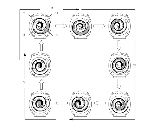
*1 Intake Port *2 Fixed Scroll *3 Variable Scroll *4 Discharge Port *a Suction *b Compression *c Discharge - -
-
-