METER / GAUGE SYSTEM
-
OUTLINE
-
An Optitron type combination meter assembly or Thin Film Transistor Liquid Crystal Display (TFT LCD) type combination meter assembly is provided depending on the model.
-
A multi-information display on which various kinds of information is displayed is integrated.
-
The combination meter assembly has a built-in meter ECU and buzzer.
-
On the Thin Film Transistor Liquid Crystal Display (TFT LCD) type combination meter assembly, an aluminum ring that is moved by a motor is provided, enabling 2 types of display.
Figure 1. Optitron Meter
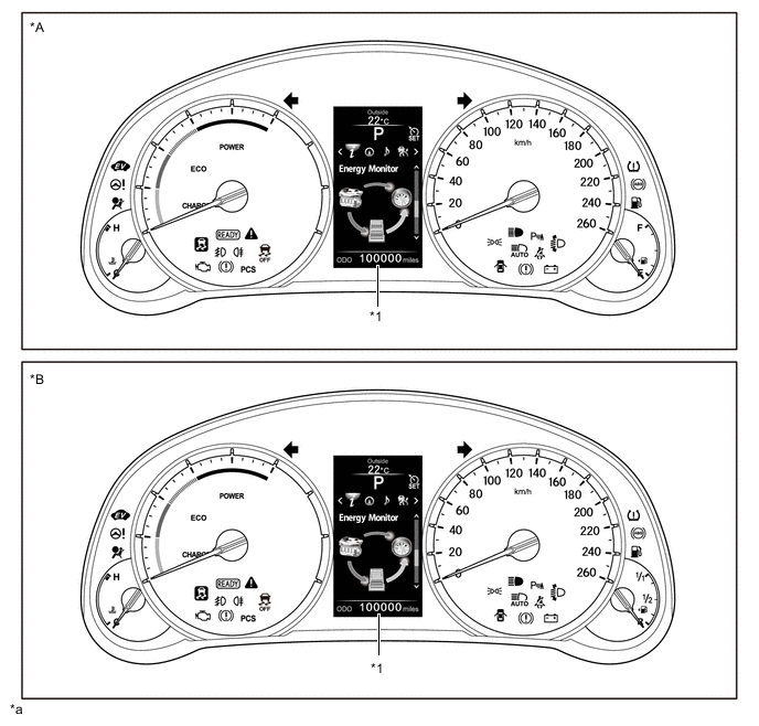
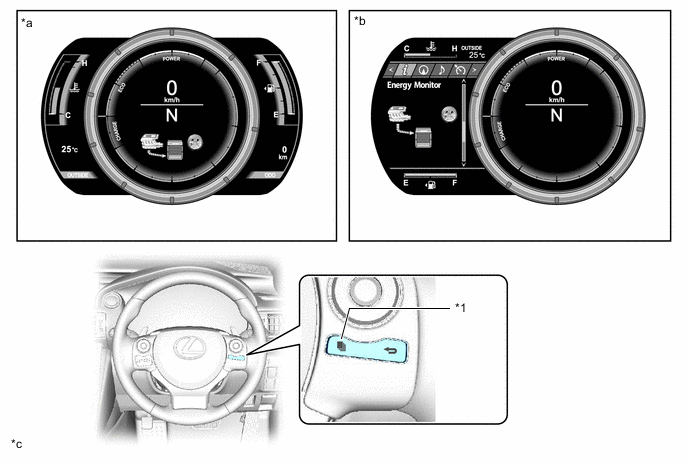
*A Except Models for Europe *B Models for Europe *1 Multi-information Display - - *a The illustration is an example that shows the locations of the indicators. - - Figure 2. TFT LCD Meter
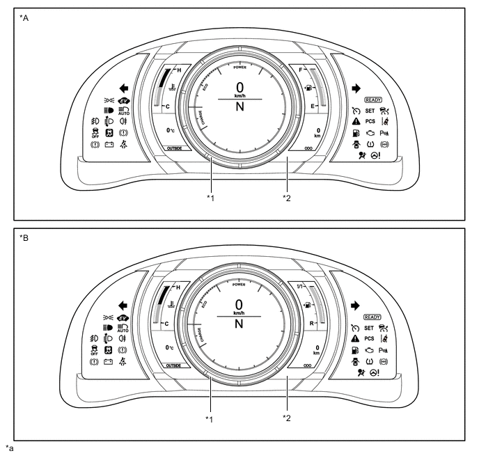
*A Except Models for Europe *B Models for Europe *1 Movable Meter Ring *2 TFT LCD *a The illustration is an example that shows the locations of the indicators. - -
-
-
MAIN FEATURES
-
Combination Meter Assembly (Optitron Meter)
-
Opening/Ending Ceremony
-
An opening ceremony which allows for anticipation of a pleasant drive is used. The opening ceremony operates as follows:
-
When the power switch is turned on (IG), the needles of the speedometer, hybrid system indicator, engine coolant temperature gauge and fuel gauge illuminate.
-
Then, the gauges and panels of the speedometer, hybrid system indicator, engine coolant temperature gauge and fuel gauge and the multi-information display illuminate.
-
When the power switch is turned off, the panels of the speedometer, hybrid system indicator, engine coolant temperature gauge and fuel gauge and the multi-information display fade out.
-
Then, the needles of the speedometer, hybrid system indicator, engine coolant temperature gauge and fuel gauge fade out.
-
Finally, the multi-information display fades out.
*a IG ON *b IG OFF
-
-
Multi-information Display
-
The multi-information display is located at the center of the combination meter assembly.
-
The multi-information display shows the following information.
Item Outline Shift Position Indicator The current shift position is displayed. Outside Temperature
-
The outside temperature is displayed.
-
When the outside temperature drops below 3°C (37°F), an ice warning lamp to warn the driver to drive with caution due to icy road conditions. After the ice warning lamp flashes 10 times, the lamp stay on. When temperature reaches 5°C (41°F), the lamp goes off.
Drive Mode
-
The currently selected drive mode is displayed:
-
ECO Mode
-
SPORT Mode
-
SNOW Mode
-
The panel color changes in accordance with driving mode:
-
ECO Mode: Blue
-
SPORT Mode: Red
Indicator/Warning Light
-
When the display conditions are met, the following indicator lights illuminate.
-
Cruise Control Indicator Light
-
Cruise Control Indicator Light (Vehicle-to-Vehicle Distance Control Mode)*3
-
Cruise SET Indicator Light
-
Lane Departure Alert Indicator Light*4
-
EV Mode Indicator Light
Information
-
The following information can be displayed on the multi-information display by switching the tabs.
-
Drive Information
-
Navigation Information
-
Audio Information
-
Dynamic Radar Cruise Control System Information*3/Lane Departure Alert System Information*4
-
Warning Message
-
Settings
-
The tab can be switched using the right/left switch in the steering pad switch assembly.
Operation Guide
-
When the following systems are operated, the operation result is displayed.
-
Headlight System
-
Wiper System
-
Dynamic Radar Cruise Control System*3
Vehicle Power Source State
-
The vehicle power source state is displayed.
-
The following indicator light is displayed on the multi-information display.
-
Smart Indicator light
ODO/TRIP Meter
-
The odometer, trip meter A or trip meter B are displayed.
-
The item shown can be switched by pressing the ODO/TRIP switch.
Light Control Rheostat Meter panel luminance can be changed. *1: Models without adaptive variable suspension system
*2: Models with adaptive variable suspension system
*3: Models with dynamic radar cruise control system
*4: Models with lane departure alert system
-
-
The drive information shows the following information.
Item Outline Drive Information
-
The items selected on the setting screen can be displayed. 4 items can be selected among the following:
-
Current Fuel Consumption (Bar Display)/Average Fuel Consumption (Mark Display)
-
Total Average Fuel Consumption Between Reset Operations
-
Average Fuel Consumption After Hybrid System Start-up
-
Average Fuel Consumption After Refueling
-
Total Average Vehicle Speed Between Reset Operations
-
Average Vehicle Speed After Hybrid System Start-up
-
Cruising Range After Hybrid System Start-up
-
Total Elapsed Time Between Reset Operations
-
Elapsed Time After Hybrid System Start-up
-
Cruising Range
-
In addition to the above functions, the following items can be displayed.
-
Energy Monitor
-
Blank
-
The item shown can be switched using the UP/DOWN switch in the steering pad switch assembly.
-
-
When audio information is being displayed, the audio system can be operated using the steering pad switch assembly.
-
-
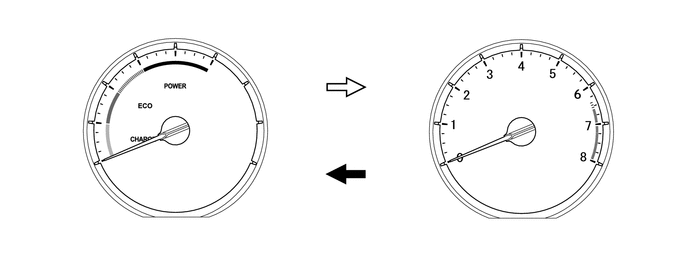
Driving Mode
-
When SPORT mode is selected, the tachometer replaces the hybrid system indicator.

SPORT Mode ON 
SPORT Mode OFF
-
-
-
Combination Meter Assembly (TFT LCD Meter)
-
Opening/Ending Ceremony
-
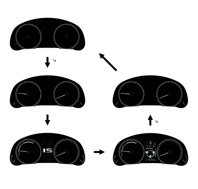
When the power switch is turned on (ACC), RPM marks of the tachometer light up in an animated sequence and in coordination with this animated display the needles of the speedometer, shift position indicator and tachometer are illuminated.
-
After the power switch is turned on (IG), the gauges, outside temperature gauge, odo/trip meter around the movable meter ring appear to emerge from the ring in an animated display. At the same time, the display inside the movable meter ring is changed to the hybrid system indicator and inside it the speedometer and shift position indicator appear.
-
When the hybrid system is started, the multi-information display is illuminated.
-
When the power switch is turned off, the speedometer and shift position indicator are turned off. At the same time, the tachometer replaces the hybrid system indicator. If the power switch is turned off while the menu screen is being displayed, the movable ring returns to the center position then the speedometer and shift position indicator are turn off.
-
At the same time as the speedometer and shift position indicator turn off, the gauges, outside temperature gauge, odo/trip meter around the movable meter ring appear to hide themselves behind the ring in an animated display.
-
Next, the tachometer needle and tachometer are turned off in sequence.
-
The odo meter remains illuminated for approximately 10 seconds before turning off.
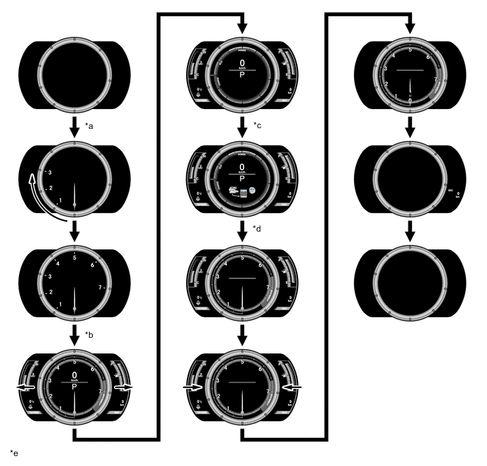
*a ACC ON *b IG ON *c Hybrid system is started. *d IG OFF *e The illustration shown are examples only. The illustrations may differ from the actual vehicle screen. - -
-
-
Normal Mode/Menu Mode
-
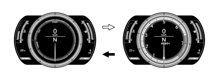
The combination meter assembly has 2 display modes: normal mode and menu mode.
-
In normal mode, the movable meter ring is positioned at the center and the tachometer, speedometer, shift position indicator and multi-information display are displayed inside of the ring. In addition, the gauges, outside temperature gauge, odo/trip meter are displayed around the ring.
-
In menu mode, the movable meter ring moves with the display to the right and the enlarged multi-information display is displayed at the left.
-
Switching to menu mode is performed using the top switch on the steering pad switch assembly. Returning to normal mode is performed using the top switch again.
*1 TOP Switch - - *a Normal Mode *b Menu Mode *c The illustration shown are examples only. The illustrations may differ from the actual vehicle screen. - -
-
-
Driving Mode
-
When SPORT S or SPORT S+ mode is selected, the tachometer replaces the hybrid system indicator.
SPORT S, SPORT S+ Mode ON SPORT S, SPORT S+ Mode OFF
-
-
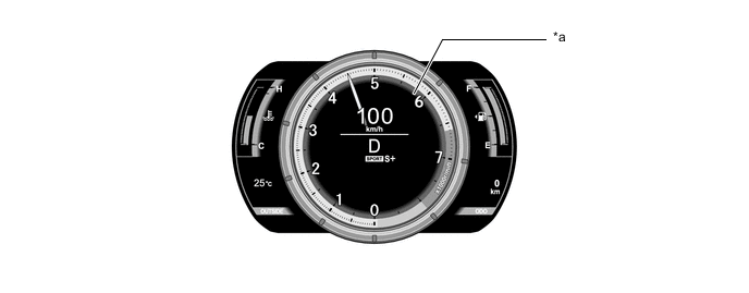
Vehicle Speed Indicator
-
The vehicle speed indicator, which informs the driver of the excess vehicle speed, is provided.
-
When the vehicle speed exceeds a set speed, a warning light is illuminated in yellow in the speed unit display area.
Tech Tips
The set speed can be changed using the setting function.
-
If the vehicle speed exceeds the predetermined speed*, a warning light is illuminated in red in the speed unit display area.
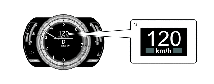
*a Vehicle speed indicator is operating - - Tech Tips
*: The predetermined vehicle speed varies according to the countries and regions. One of the following is set as a predetermined speed.
-
120 km/h: Destination package for Taiwan
-
160 km/h (100 mph): Destination package for United Kingdom
-
200 km/h (125 mph): Except destination package for Taiwan and United Kingdom
-
-
-
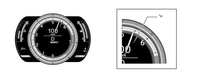
Rev Indicator
-
When the engine speed exceeds a set level, the rev indicator (yellow ring) is illuminated in the tachometer.
-
If the engine speed exceeds 6000 rpm, the rev indicator (red ring) is illuminated in the tachometer.
*a Rev Indicator - -
-
-
Tachometer Peak Hold Display
-
The tachometer peak hold display, which displays the afterimage of the tachometer needle at the maximum engine speed, is provided.
-
If engine speed is changed due to shift change operation, the afterimage of the maximum engine speed is displayed for 0.5 seconds.
-
This function operates when engine speed is 4000 rpm or more.
*a Tachometer Peak Hold Display - -
-
-
Multi-information Display
-
During normal mode, the multi-information display is displayed inside of the movable meter ring and, during menu mode, is displayed at the left side of the combination meter assembly.
-
The multi-information display shows the following information.
Normal Mode Item Outline Drive Information
-
The following items can be displayed. The 4 display items can be selected in the setting screen:
-
Current Fuel Consumption (Bar Display)/Average Fuel Consumption (Mark Display)
-
Total Average Fuel Consumption Between Reset Operations
-
Average Fuel Consumption After Hybrid System Start-up
-
Average Fuel Consumption After Refueling
-
Total Average Vehicle Speed Between Reset Operations
-
Average Vehicle Speed After Hybrid System Start-up
-
Cruising Range After Hybrid System Start-up
-
Total Elapsed Time Between Reset Operations
-
Elapsed Time After Hybrid System Start-up
-
Cruising Range
-
In addition to the above functions, the following items can be displayed.
-
Energy Monitor
-
Blank
-
The item shown can be switched using the UP/DOWN switch in the steering pad switch assembly.
Menu Mode Item Outline Information
-
The following information can be displayed on the multi-information display by switching the tabs.
-
Drive Information
-
Navigation Information
-
Audio Information
-
Dynamic Radar Cruise Control System*1/Lane Departure Alert System*2 Information
-
Warning Message
-
Settings
-
The tab can be switched using the right/left switch in the steering pad switch assembly.
*1: Models with dynamic radar cruise control system
*2: Models with lane departure alert system
-
-
The drive information shows the following information.
Item Outline Drive Information
-
The following items can be displayed. The 4 display items can be selected in the setting screen:
-
Current Fuel Consumption (Bar Display)/Average Fuel Consumption (Mark Display)
-
Total Average Fuel Consumption Between Reset Operations
-
Average Fuel Consumption After Hybrid System Start-up
-
Average Fuel Consumption After Refueling
-
Total Average Vehicle Speed Between Reset Operations
-
Average Vehicle Speed After Hybrid System Start-up
-
Cruising Range After Hybrid System Start-up
-
Total Elapsed Time Between Reset Operations
-
Elapsed Time After Hybrid System Start-up
-
Cruising Range
-
In addition to the above functions, the following items can be displayed.
-
Energy Monitor
-
Blank
-
The item shown can be switched using the UP/DOWN switch in the steering pad switch assembly.
-
-
When audio information is being displayed, the audio system can be operated using the steering pad switch assembly.
-
-
-
Hybrid System Indicator
-
The Hybrid System Indicator displays the total of the HV battery and engine output as the hybrid system output.
-
The scale for the Hybrid System Indicator is divided into 3 areas (Charge, Eco, Power). The role of each area is as follows.
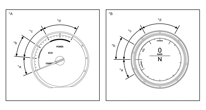
*A Optitron Meter *B TFT LCD Meter *a Charge Area *b Hybrid Eco Area *c Eco Area *d Power Area Information Displayed in Hybrid System Indicator Area Function Charge The Charge area indicates when energy is being regenerated. Eco
-
The Eco area indicates when the vehicle is being driven in an Eco-friendly manner.
-
The Hybrid Eco area indicates that the vehicle is driven in a manner that promotes frequent motor only operation. (Based on various conditions, the power management control ECU controls if the engine should be stopped to enhance fuel efficiency.)
Power The Power area indicates that the Eco-friendly driving range is being exceeded (during full power driving, etc.). -
-
-