HYBRID TRANSMISSION SYSTEM
-
CONSTRUCTION
-
Compact, lightweight permanent magnet synchronous motors are used for MG1 and MG2.
-
MG1 charges the HV battery and supplies power to drive the vehicle, and is also used as a starter to start the engine. In addition, MG1 reduces engine speeds to smoothly stop the engine.
-
MG2 assists engine output as an additional power source working in conjunction with the engine, and operates separately depending on the situation realizing excellent power performance such as smooth starting and acceleration.
-
The MG ECU receives signals from the power management control ECU and based on this command, it switches the Insulated Gate Bipolar Transistors (IGBT) in the Power Modules (PM) to drive MG1 and MG2.
-
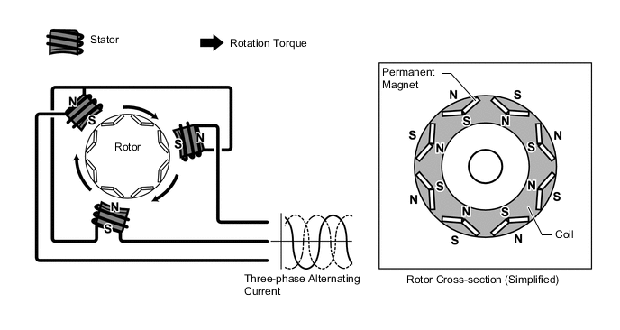
When three-phase alternating current is applied to the three-phase winding of the stator coil, rotation of the magnetic field is created in the motor. This rotation of the magnetic field is controlled based on the rotation position and speed of the rotor to pull the permanent magnet located in the rotor towards the magnetic field, thereby producing torque. This torque is almost in proportion to the current, and the speed is controlled based on the frequency of the alternating current. In addition, the rotation of the magnetic field and the angle of the rotor magnet are accurately controlled to efficiently generate high torque even in the high-speed range.
-
For MG1 and MG2, the permanent magnets in the rotors are optimally located to efficiently use reluctance torque*. This amplifies the rotational force of the rotor, helping to enhance driving force.
Tech Tips
*: Torque generated due to the changes in magnetic reluctance in the gap between the stator and rotor
-
When generating power, rotation of the rotor creates a magnetic field, inducing current flow in the stator coil.
Figure 1. MG1 Power Generation
-
Rotation sensor (Resolver type)
-
The resolver type rotation sensors are compact, reliable sensors, which accurately detect the location of the magnets, which is requisite to efficiently control MG1 and MG2.
-
The stator of a rotation sensor employs 3 coils as shown in the illustration. Output coils S and coil C are arranged at an angle of 90° to each other.
-
This sensor applies a certain amount of alternating current to excitation coil A so that a certain level of frequency is constantly applied to coil S and coil C regardless of the rotation speed of the rotor. Because the rotor is in an oval shape, the size of the gap between the stator and the rotor varies as the rotor rotates. As a result of this, peak values of the output waveforms of coil S and coil C fluctuate in response to the position of the rotor.
-
The MG ECU always detects those peak values. It then connects those values to create a theoretical waveform. The absolute position of the rotor is estimated based on the difference between the values of coil S and coil C, the rotation direction is determined based on the phase difference of the theoretical waveforms of coil S and coil C, and the rotation speed is estimated based on the angular change of the rotor within a certain amount of time.
-
The following illustration shows waveforms of coil A, coil S and coil C when the rotor rotates by 180° in the positive direction.
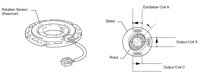
Figure 2. Rotation Sensor Output Waveform (Conceptual Image Shown)
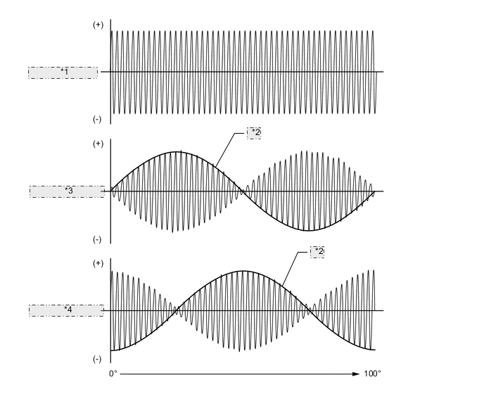
*1 Excitation Coil A *2 Theoretical Waveform *3 Excitation Coil S *4 Excitation Coil C
-
-
Temperature sensor
-
A temperature sensor is provided respectively for MG1 and MG2 to detect the stator temperature.
-
The power management control ECU performs hybrid system control based on the signal from these temperature sensors.
Figure 3. Sensor Characteristics
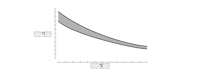
*1 Resistance *2 Temperature
-
-