EMISSION CONTROL SYSTEM
-
FUNCTION OF MAIN COMPONENTS
-
The main components of the exhaust emission control system are as follows:
Component Function TWC Oxidizes CO and HC in the exhaust gas and deoxidizes NOx at the same time, to purify them into CO2, H2O and N2.
Oxygen Sensor The signal of the air fuel ratio sensor changes abruptly between lean and rich at the stoichiometric air fuel ratio. Located downstream of the catalytic converter. Air Fuel Ratio Sensor Is used to determine the concentration of oxygen remaining in the exhaust gas. Has a characteristic where its output is proportional to the engine air fuel ratio. Located upstream of the catalytic converter. ECM Controls the volume of fuel consumed based primarily on the signal from the air fuel ratio sensor, with minor corrections based on the signal from the oxygen sensor. This control optimizes the exhaust emissions. -
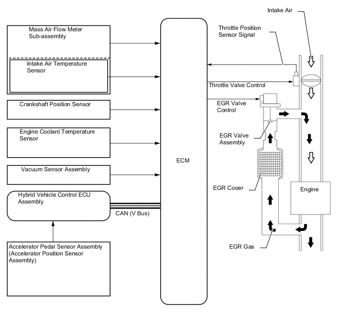
The main components of the EGR system are as follows (Models with EGR System):
Component Function Vacuum Sensor Assembly Detects the pressure in the intake manifold and sends signals to the ECM for EGR control. EGR Valve Assembly Opens and closes based on signals from the ECM and controls the flow rate of the exhaust gas in the EGR bypass. EGR Cooler Assembly The EGR cooler cools the exhaust gas to improve EGR efficiency. Hybrid Vehicle Control ECU Assembly Sends signals such as the accelerator pedal position sensor signal to the ECM. ECM Based on the signals received from the sensors, the ECM determines the EGR volume in accordance with the engine operating conditions. -
The main components of the blowby gas ventilation system are as follows:
Component Function PCV Valve (Ventilation Valve Sub-assembly) Opens and closes using vacuum generated in the intake manifold and controls the flow rate of the blowby gas. Oil Separator (Ventilation Case Sub-assembly) Collects oil mist in the blowby gas, reducing the oil consumption.
-
-
SYSTEM CONTROL
-
EGR Control (Models with EGR System)
-
For the EGR system, an amount of EGR gas, which is regulated in accordance with the engine conditions, is allowed to flow into the intake passage, reducing the peak temperature in the engine combustion chamber and achieving low fuel consumption.
-
By sensing the engine driving conditions and actual amount of the EGR valve assembly opening, the ECM operates the EGR valve assembly and throttle control motor, to regulate the amount of exhaust gas that is recirculated.
-
A highly efficient EGR cooler assembly is used to achieve the optimized EGR rate.
-
EGR chambers are provided in the intake manifold so that EGR gas is equally distributed to the cylinders.
-
-
Blowby gas ventilation system
-
By introducing blowby gas that has a large amount of HC into the intake manifold for combustion, the system prevents the blowby gas, which includes a large amount of HC, from being discharged into the atmosphere. The amount of airflow through the crankcase (blowby gas introduction volume) is controlled according to the engine operating conditions. This prevents the excessive consumption of engine oil, and is a factor in idle speed control.
-
This system uses the ventilation method, which sucks the blowby gas directly from the stiffening crankcase assembly, enhancing the ventilation efficiency.
-
An oil separator (ventilation case sub-assembly) is provided in the blowby gas passage inside the cylinder head cover sub-assembly. This separates the engine oil from the blowby gas in order to reduce oil degradation and reduce the amount of engine oil consumed.
-
The Positive Crankcase Ventilation (PCV) valve (ventilation valve sub-assembly) passage returns the blowby gas into the intake manifold in accordance with the intake manifold vacuum.
-
Under light load conditions, the intake manifold vacuum causes the blowby gas to be drawn via the PCV valve into the intake manifold.
-
Under high load conditions, the introduction of fresh air is stopped, allowing a large amount of blowby gas to be drawn into the intake system.
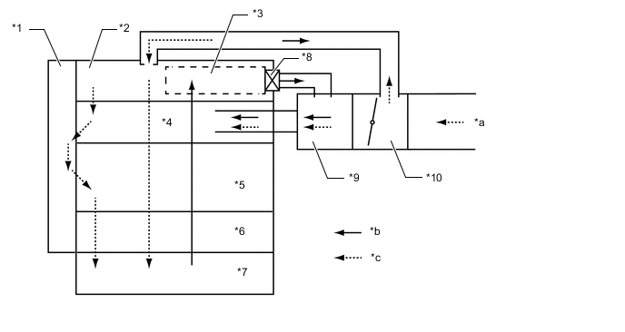
*1 Timing Chain Cover Assembly *2 Cylinder Head Cover Sub-assembly *3 Oil Separator (Ventilation Case Sub-assembly) *4 Cylinder Head Sub-assembly *5 Cylinder Block Sub-assembly *6 Stiffening Crankcase Assembly *7 Oil Pan Sub-assembly *8 PCV Valve (Ventilation Valve Sub-assembly) *9 Intake Manifold *10 Throttle Body with Motor Assembly *a from Air Cleaner Assembly *b Blowby Gas *c Fresh Air - -
-
-