FUEL SYSTEM
-
CONSTRUCTION
-
The fuel pump assembly (for high pressure) is composed of an electromagnetic spill valve that adjusts the discharge amount of high pressurized fuel, a plunger that is driven by the intake camshaft to pressurize fuel, a check valve that mechanically opens and closes the path to the fuel delivery pipe sub-assembly (for direct injection) and a fuel relief valve that releases the fuel when a malfunction is detected in the high-pressure fuel system. In addition, to reduce fuel pulsations, a fuel pressure pulsation damper assembly is installed at the inlet for low pressure fuel flowing from the fuel tank assembly.
-
A roller lifter (fuel pump lifter assembly) is provided to cope with higher output performance and higher pressurized fuel.
-
The plunger is moved up and down by a lobe that is located at the rear end of the intake camshaft of the engine. This lobe causes 3 strokes of the pump piston to occur for each camshaft revolution (3 protrusions exist 120 degrees from each other on the same camshaft "lobe").
-
The pressure of highly pressurized fuel is adjusted between 2.75 to 18 MPa in accordance with the vehicle driving conditions, reducing friction loss.
-
A spill control valve is used to control the pump discharge pressure. The spill control valve is located in the inlet passage of the fuel pump assembly (for high pressure). The valve is electrically opened and closed by the EDU, based on instructions from the ECM.
-
A check valve is present in the outlet of the fuel pump assembly (for high pressure). As the pressure in the outlet of the pump rises and becomes high enough to push the check valve off its seat, fuel will begin to flow to the fuel delivery pipe sub-assembly (for direct injection) (minimum pressure to open the check valve is 60 kPa).
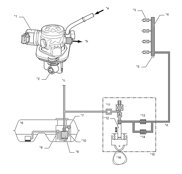
*1 Spill Control Valve *2 Roller Lifter (Fuel Pump Lifter Assembly) *3 Fuel Injector Assembly (for Direct Injection) *4 Fuel Delivery Pipe Sub-assembly (for Direct Injection) *5 Fuel Pressure Sensor *6 Fuel Tank Assembly *7 Fuel Pressure Regulator Assembly *8 Jet Pump *9 Fuel Pump Assembly (for Low Pressure) *10 Fuel Filter Assembly *11 Fuel Pressure Pulsation Damper Assembly *12 Plunger *13 Check Valve (60 kPa) *14 Fuel Relief Valve (23.6 MPa) *15 Fuel Pump Assembly (for High Pressure) *16 Intake Camshaft (Cam to Drive Fuel Pump) *a Low-pressure Fuel (from Fuel Pump Assembly (for Low Pressure)) *b High-pressure Fuel (to Fuel Delivery Pipe Sub-assembly (for Direct Injection)) *c to Fuel Delivery Pipe Sub-assembly (for Port Injection) *d High-pressure Fuel Pipe
-
-
OPERATION
-
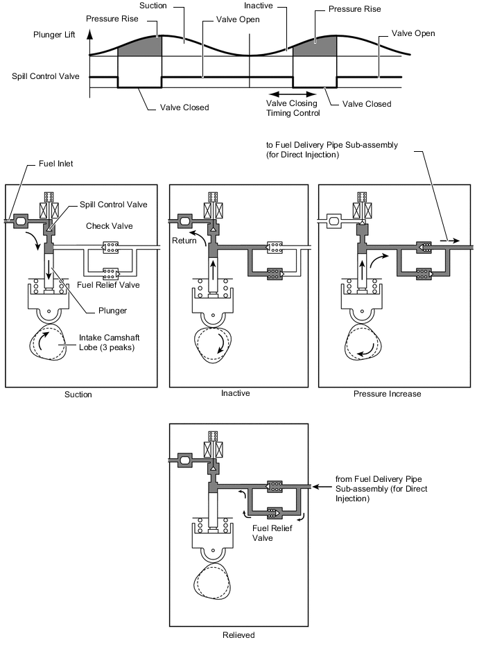
During the intake portion of the pump cycle, the spill control valve is opened, and the pump plunger (piston) is moved downward by spring force. This allows fuel to be drawn into the cylinder of the pump. If the spill control valve has not been closed yet, when the cam forces the plunger to move upward, the fuel in the pump cylinder (this fuel is not pressurized) will be pushed back to the pump inlet (fuel tank side).
-
In order to close the spill control valve as the piston is moving upward, the ECM sends a signal to the valve via the EDU. When the spill control valve is closed and the plunger is moving upward, the pressure in the pump cylinder will rise. As this pressure rises above 60 kPa (or the pressure of the delivery pipe, whichever is higher), the fuel will begin to flow to the fuel delivery pipe sub-assembly (for direct injection). The ECM calculates the target fuel pressure based on driving conditions. The ECM controls the pressure by operating the spill control valve via the EDU. The timing and duration of the spill control valve closing are varied to cause the pump pressure to meet the target pressure.
-
If the fuel pressure in the high-pressure fuel pipes is abnormally high, the relief valve discharges some of fuel in order to limit the pressure.
-