HYBRID BATTERY SYSTEM
-
CONSTRUCTION
-
The battery voltage sensor, hybrid battery junction block assembly and service plug grip are positioned at the vehicle front side of the HV battery module. This achieves a compact design for the HV battery pack so that it can be accommodated in the spare tire area in the luggage compartment, thereby realizing a larger luggage compartment capacity and excellent usability.
-
The service plug grip is provided to shut off the internal circuit of the HV battery.
-
The battery cooling blower assembly is used as a dedicated cooling system to ensure that the HV battery performs properly, despite it generating significant heat during the repetitive charge and discharge cycles.
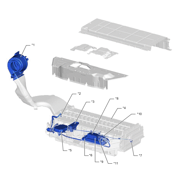
*1 Battery Cooling Blower Assembly *2 HV Battery Intake Air Temperature Sensor *3 Service Plug Grip *4 HV Battery (Battery Modules) *5 Battery Voltage Sensor *6 Hybrid Battery Junction Block Assembly *7 HV Battery Temperature Sensor *8 SMRB *9 SMRG *10 SMRP *11 Battery Current Sensor - - -
Battery Module
-
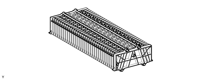
The HV battery consists of 32 separate battery modules. They are connected to each other in series through 2 bus bar modules.
-
These battery modules are each made up of 6 cells. The HV battery has a total of 192 cells (6 cells x 32 modules) and a nominal voltage of 230.4 V (1.2 V x 192 cells).
-
-
HV Battery Temperature Sensor and HV Battery Intake Air Temperature Sensor
-
There are 3 HV battery temperature sensors and 1 HV battery intake air temperature sensor.
-
The hybrid vehicle control ECU assembly optimally controls the cooling system so that the HV battery temperature can be within a specified range according to the temperature information that is received via the battery voltage sensor.
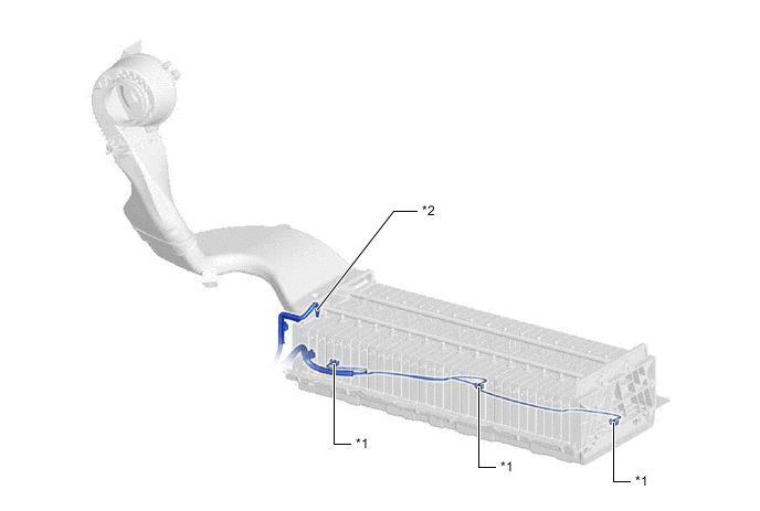
*1 HV Battery Temperature Sensor *2 HV Battery Intake Air Temperature Sensor
-
-