HYBRID CONTROL SYSTEM
-
OPERATION
-
Operation of Hybrid Vehicle
-
The hybrid system uses motive force provided by the engine and motor (MG2), and uses generator (MG1). The system optimally combines these forces in accordance with various driving conditions.
-
The hybrid vehicle control ECU assembly constantly monitors the engine coolant temperature, SOC, HV battery temperature and electrical load conditions. If any of the monitoring conditions fail to satisfy the requirements, the power switch is on (READY) and the shift position is any position other than N, the hybrid vehicle control ECU assembly starts the engine.
-
The hybrid system drives the vehicle by optimally combining the operation of the engine, generator (MG1) and motor (MG2) in accordance with the driving conditions listed below. The vehicle conditions listed below are examples of typical vehicle driving conditions.
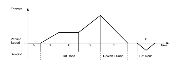
Driving Condition A Power switch on (READY) B Starting Off C Constant-speed Cruising D During Full Throttle Acceleration E During Deceleration F During Reverse
-
-
Driving Condition A: READY-ON State
-
Even if the driver turns the power switch on (READY), sometimes the engine will not start. If this happens, the engine, generator (MG1) and motor (MG2) remain stopped. The engine will only start if conditions such as engine coolant temperature, SOC of the HV battery, HV battery temperature and electrical load require an engine start.
-
After driving, if the driver stops the vehicle and moves the shift lever to P, the hybrid vehicle control ECU assembly will continue to operate the engine. The engine will continue to operate until SOC of the HV battery, engine coolant temperature, HV battery temperature and/or electrical load conditions reach a specified level.
-
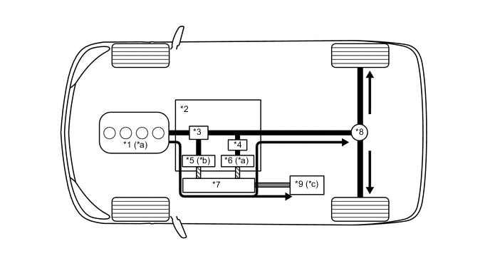
If any of the items monitored by the hybrid vehicle control ECU assembly indicates the need for an engine start when the READY indicator light is on and the shift lever is in P, the hybrid vehicle control ECU assembly will activate generator (MG1) to start the engine.
-
While the engine is cranking, to prevent the reactive force of the sun gear of generator (MG1) from rotating the ring gear and driving the drive wheels, current is also applied to motor (MG2) in order to prevent motor (MG2) from rotating. This function is called "reactive control".
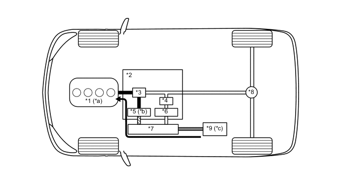
*1 Engine *2 Hybrid Vehicle Transmission Assembly *3 Power Split Planetary Gear *4 Motor Speed Reduction Planetary Gear *5 Generator (MG1) *6 Motor (MG2) *7 Inverter with Converter Assembly *8 Differential *9 HV Battery - - *a Driven *b Drive *c Discharge - - 
Power Transmission 
Mechanical Power Path 
Electrical Power Path (DC) 
Electrical Power Path (AC) -
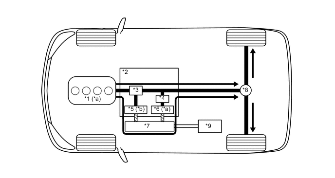
If the SOC of the HV battery is low, it is charged by generator (MG1) which is driven by the engine.
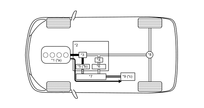
*1 Engine *2 Hybrid Vehicle Transmission Assembly *3 Power Split Planetary Gear *4 Motor Speed Reduction Planetary Gear *5 Generator (MG1) *6 Motor (MG2) *7 Inverter with Converter Assembly *8 Differential *9 HV Battery - - *a Drive *b Driven - Generates Electricity *c Charged by Generator (MG1) - - Power Transmission Mechanical Power Path Electrical Power Path (DC) Electrical Power Path (AC)
-
-
Driving Condition B: Starting Off
-
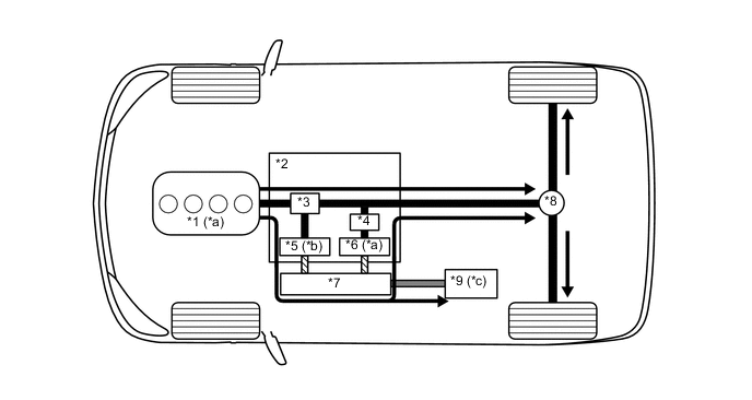
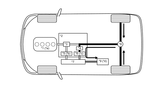
When the vehicle is started off, the vehicle operates powered by motor (MG2).
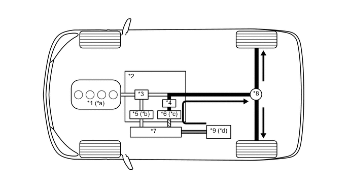
*1 Engine *2 Hybrid Vehicle Transmission Assembly *3 Power Split Planetary Gear *4 Motor Speed Reduction Planetary Gear *5 Generator (MG1) *6 Motor (MG2) *7 Inverter with Converter Assembly *8 Differential *9 HV Battery - - *a Stopped *b Rotates Freely *c Drive *d Discharge Power Transmission Mechanical Power Path Electrical Power Path (DC) Electrical Power Path (AC) -
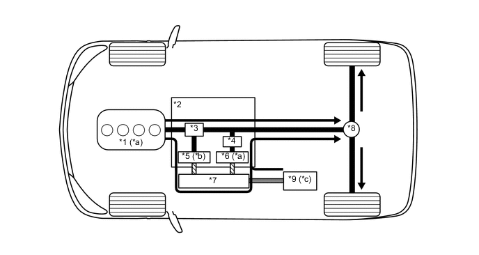
If the SOC of the HV battery is low, it is charged by generator (MG1) which is driven by the engine. The electricity from generator (MG1) is also used to drive motor (MG2).
*1 Engine *2 Hybrid Vehicle Transmission Assembly *3 Power Split Planetary Gear *4 Motor Speed Reduction Planetary Gear *5 Generator (MG1) *6 Motor (MG2) *7 Inverter with Converter Assembly *8 Differential *9 HV Battery - - *a Drive *b Driven - Generates Electricity *c Charged by Generator (MG1) - - Power Transmission Mechanical Power Path Electrical Power Path (DC) Electrical Power Path (AC)
-
-
Driving Condition C: during Low Load and Constant-speed Cruising
-
When the vehicle is running under constant-speed cruising conditions, the engine will be operated in its most efficient range to power the vehicle.
-
The motive force from the engine is split into two in the power split planetary gear. One portion of the motive force is used to drive the wheels directly and the other is used to generate electricity using generator (MG1).
-
The electricity from generator (MG1) is used to drive motor (MG2). This supports the directly transmitted engine motive force, contributing to fuel efficiency.
*1 Engine *2 Hybrid Vehicle Transmission Assembly *3 Power Split Planetary Gear *4 Motor Speed Reduction Planetary Gear *5 Generator (MG1) *6 Motor (MG2) *7 Inverter with Converter Assembly *8 Differential *9 HV Battery *10 - *a Drive *b Driven - Generates Electricity Power Transmission Mechanical Power Path Electrical Power Path (AC) - - -
If the SOC of the HV battery is low, more engine power is provided to increase the generation of electricity via generator (MG1). This charges the HV battery.
*1 Engine *2 Hybrid Vehicle Transmission Assembly *3 Power Split Planetary Gear *4 Motor Speed Reduction Planetary Gear *5 Generator (MG1) *6 Motor (MG2) *7 Inverter with Converter Assembly *8 Differential *9 HV Battery - - *a Drive *b Driven - Generates Electricity *c Charged by Generator (MG1) - - Power Transmission Mechanical Power Path Electrical Power Path (DC) Electrical Power Path (AC)
-
-
Driving Condition D: during Full Throttle Acceleration
-
When the vehicle driving condition changes from low load cruising to full throttle acceleration, the system supplements the motive force of motor (MG2) with electrical power from the HV battery.
*1 Engine *2 Hybrid Vehicle Transmission Assembly *3 Power Split Planetary Gear *4 Motor Speed Reduction Planetary Gear *5 Generator (MG1) *6 Motor (MG2) *7 Inverter with Converter Assembly *8 Differential *9 HV Battery - - *a Drive *b Driven - Generates Electricity *c Discharge - - Power Transmission Mechanical Power Path Electrical Power Path (DC) Electrical Power Path (AC)
-
-
Driving Condition E: during Deceleration
-
While the vehicle is being driven with the shift lever in D and it decelerates, the engine turns off and the engine motive force output to the wheels will be zero. At this time, the wheels drive motor (MG2), causing motor (MG2) to operate as a generator and charge the HV battery. While motor (MG2) is operating as a generator, it creates a resistance to rotation at the wheels, producing a braking effect.
-
If the vehicle decelerates at a higher speed, the engine (crankshaft) will not stop turning. The engine will maintain a predetermined speed in order to protect the planetary gear unit. This operation is not shown in the following diagrams:
*1 Engine *2 Hybrid Vehicle Transmission Assembly *3 Power Split Planetary Gear *4 Motor Speed Reduction Planetary Gear *5 Generator (MG1) *6 Motor (MG2) *7 Inverter with Converter Assembly *8 Differential *9 HV Battery - - *a Stopped *b Rotates Freely *c Driven - Generates Electricity *d Charged by Motor (MG2) Power Transmission Mechanical Power Path Electrical Power Path (DC) Electrical Power Path (AC)
-
-
Driving Condition F: Driving in Reverse
-
While the vehicle is being driven in reverse, its power is delivered by motor (MG2). At this time, motor (MG2) is spinning in the opposite (-) direction of forward travel, the engine can remain stopped, and generator (MG1) is spinning in the (+) direction without generating electricity.
-
While driving in reverse, when any of the conditions monitored by the hybrid vehicle control ECU assembly, such as the SOC of the HV battery, HV battery temperature, engine coolant temperature and electrical load condition, reach a specified level, generator (MG1) will be used to start the engine. The following illustration represents an example when the engine is not running:
*1 Engine *2 Hybrid Vehicle Transmission Assembly *3 Power Split Planetary Gear *4 Motor Speed Reduction Planetary Gear *5 Generator (MG1) *6 Motor (MG2) *7 Inverter with Converter Assembly *8 Differential *9 HV Battery - - *a Stopped *b Rotates Freely *c Drive *d Discharge Power Transmission Mechanical Power Path Electrical Power Path (DC) Electrical Power Path (AC)
-
-