HYBRID CONTROL SYSTEM
-
SYSTEM CONTROL
-
Boost Converter Control
-
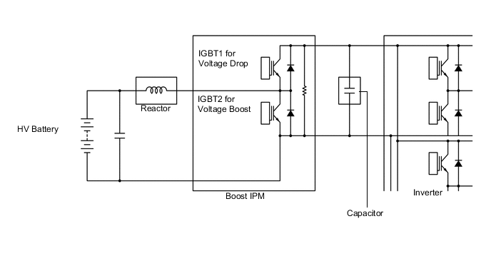
The boost converter boosts the HV battery nominal voltage of DC 230.4 V up to a maximum voltage of DC 650 V, in accordance with the signals provided by the power management control ECU via the MG ECU.
-
The inverter converts the alternating current generated by generator (MG1) or motor (MG2) into direct current. The boost converter steps down the generated voltage of DC 650 V (maximum voltage) to approximately DC 230.4 V, in accordance with the signals provided by the power management control ECU via the MG ECU.
-
The boost converter consists of the boost IPM with built-in IGBTs that perform switching control, the reactor that stores the electrical power and generates the electromotive force, and the capacitor that charges and discharges the boosted high-voltage electricity.
-
The flow of the boost converter boosting is as described below.
Step Outline 1 IGBT2 turns on, causing the voltage of the HV battery (nominal voltage of DC 230.4 V) to charge the reactor. As a result, the reactor stores the electrical power. 2 IGBT2 turns off, causing the reactor to produce an electromotive force (the current continues to flow from the reactor). This electromotive force causes the voltage to rise to a maximum voltage of DC 650 V. Induced by the electromotive force that is created by the reactor, the current that is flowing from the reactor flows into the inverter and the capacitor at the boosted voltage. 3 IGBT2 turns on again to cause the voltage of the HV battery to charge the reactor. While this happens, by discharging the electrical power (maximum voltage of DC 650 V) stored in the capacitor, electrical power continues to be supplied to the inverter. 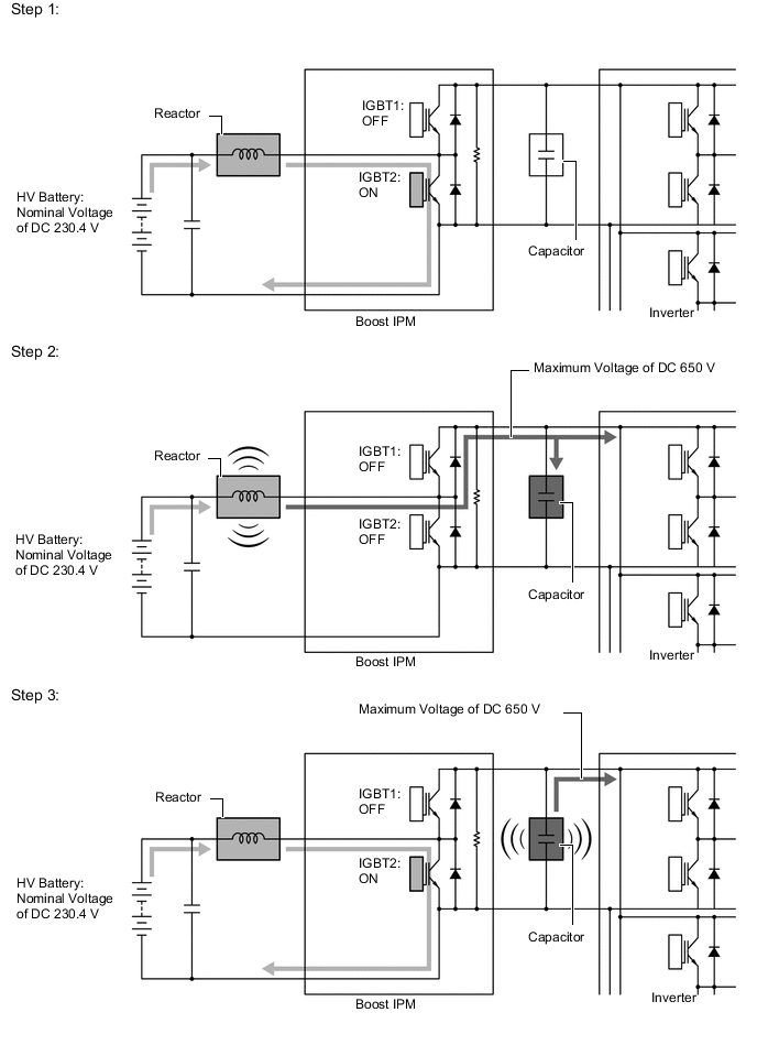
-
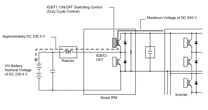
The alternating current which is generated by generator (MG1) or motor (MG2) for the purpose of charging the HV battery is converted into direct current (maximum voltage of DC 650 V) by the inverter. Then, the boost converter is used to step down the voltage to approximately DC 230.4 V. This is accomplished by IGBT1 being switched on and off using duty cycle control, intermittently interrupting the electrical power provided to the reactor by the inverter.
-
-
DC-DC Converter Control
-
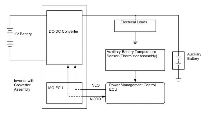
The DC-DC converter steps down the HV battery nominal voltage of DC 230.4 V to approximately DC 14 V in order to supply electricity to the electrical components, as well as to recharge the auxiliary battery.
-
In order to regulate the output voltage from the DC-DC converter, the power management control ECU transmits an output voltage request signal to the DC-DC converter in response to auxiliary battery temperature sensor signals.
-
-