HYBRID CONTROL SYSTEM
-
SYSTEM CONTROL
-
Hybrid Vehicle Control
-
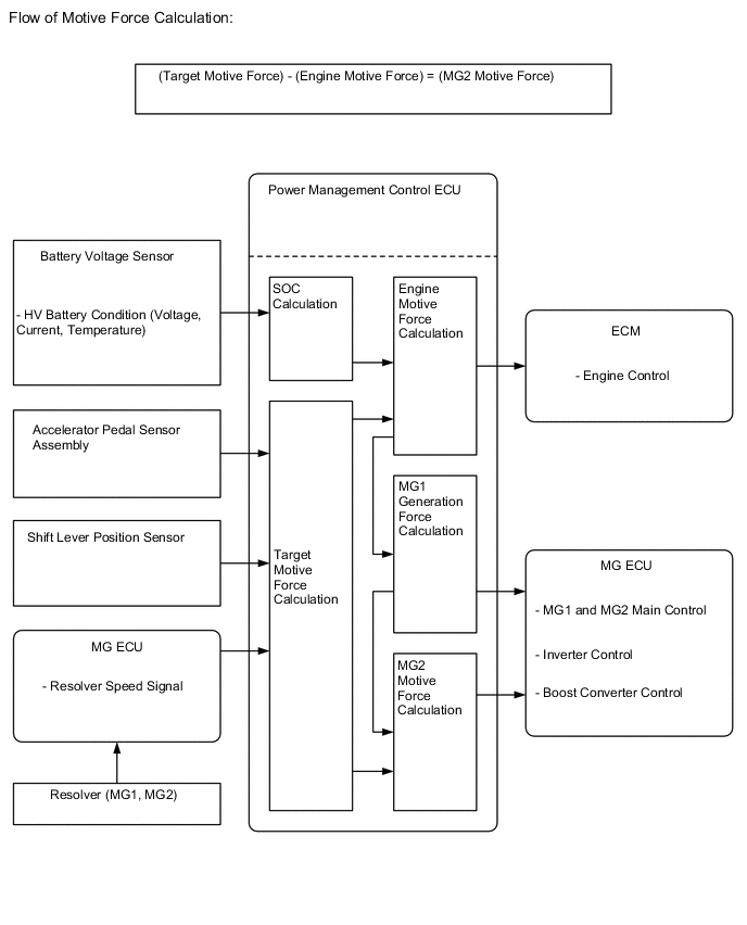
The power management control ECU detects the degree to which the accelerator pedal is depressed using the signals from the accelerator pedal sensor assembly and detects the shift position signals from the shift lever position sensor. The power management control ECU receives the speed signals from the generator (MG1) and motor (MG2) resolvers via the MG ECU. The power management control ECU determines the driving conditions of the vehicle in accordance with this information, and optimally controls the motive forces of generator (MG1), motor (MG2) and the engine. Furthermore, the power management control ECU optimally controls the output and torque of generator (MG1), motor (MG2) and the engine in order to deliver lower fuel consumption and cleaner exhaust emissions.
-
The power management control ECU calculates the engine motive force based on the calculated target motive force, and by taking the SOC and the temperature of the HV battery into consideration. The value obtained by subtracting the engine motive force from the target motive force is the motor (MG2) motive force.
-
The ECM performs control of the engine in accordance with the target engine speed and required engine motive force received from the power management control ECU. Furthermore, the power management control ECU appropriately operates generator (MG1) and motor (MG2) in order to provide the required generator (MG1) generation force and the required motor (MG2) motive force.
-
-
SOC Control
-
The power management control ECU calculates the SOC of the HV battery based on the charge/discharge amperage detected by the battery current sensor. The power management control ECU constantly performs charge/discharge control based on the calculated SOC in order to maintain the SOC within its target range.
-
While the vehicle is in motion, the HV battery undergoes repetitive charge/discharge cycles, as it becomes discharged by motor (MG2) during acceleration and charged by regenerative braking during deceleration.
-
When the SOC is below the lower level, the power management control ECU increases the power output of the engine to operate generator (MG1), which charges the HV battery.
-
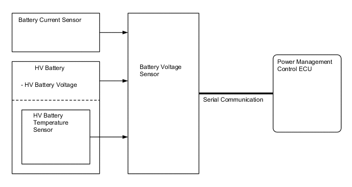
The battery voltage sensor converts the HV battery related signals (voltage, current and temperature) into digital signals, and transmits them to the power management control ECU via serial communication. These signals are needed to determine the SOC that is calculated by the power management control ECU.
-
-
Engine Control
-
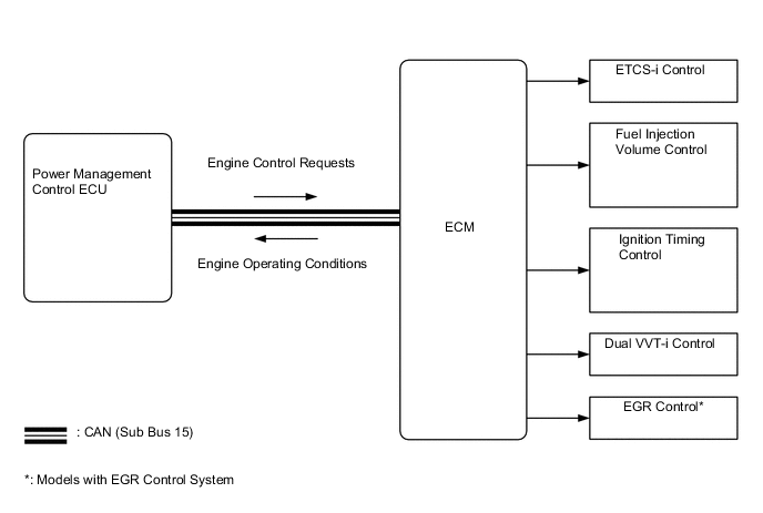
The ECM receives the target engine speed and required engine motive force, which were sent from the power management control ECU, and controls the ETCS-i, fuel injection volume, ignition timing, Dual VVT-i and EGR*.
*: Models with EGR system
-
The ECM transmits the operating conditions of the engine to the power management control ECU.
-
Upon receiving the engine stop signal from the power management control ECU in accordance with the basic hybrid vehicle control, the ECM will stop the engine.
-
-
System Main Relay Control
-
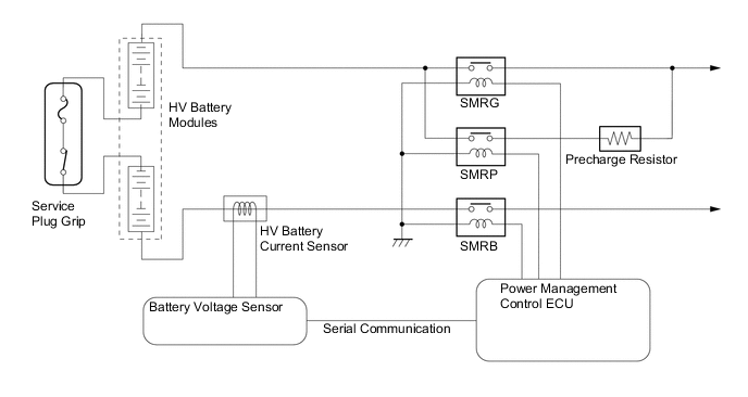
The power management control ECU controls the system main relays to connect and disconnect the high-voltage circuit from the HV battery. The power management control ECU also uses the timing of the operation of the system main relays to monitor the operation of the relay contacts.
-
A total of 3 relays, 1 for the positive side (SMRB), and 2 for the negative side (SMRP, SMRG), are provided to ensure proper operation.
-
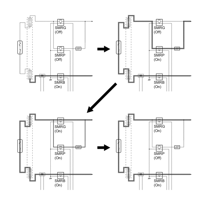
When the hybrid system changes to the READY-on state, the power management control ECU turns on SMRB and SMRP in sequence, and applies the current through the precharge resistor. After that, it turns SMRG on, and applies the current by bypassing the precharge resistor. Then it turns SMRP off. As the controlled current is initially allowed to pass through the precharge resistor in this manner, the contact point in the circuit is protected from damage that could be caused by an inrush current.
-
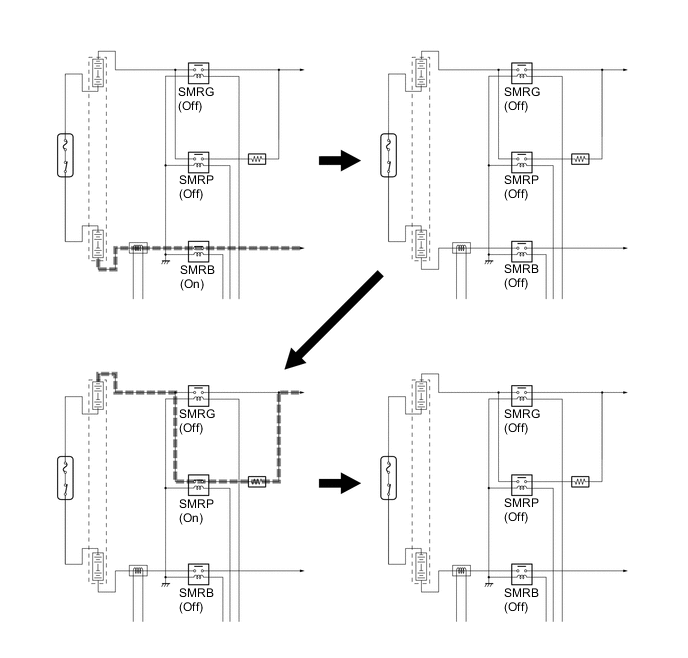
When the hybrid system changes to a state other than the READY-on state, the power management control ECU turns SMRG off first. Next, it turns SMRB off after determining whether or not SMRG is operating properly. After that, it turns on SMRP and then off after determining whether or not SMRB is operating properly. As a result, the power management control ECU verifies that the respective relays have been properly turned off.
-
-
Cooling System Control for Inverter with Converter Assembly
-
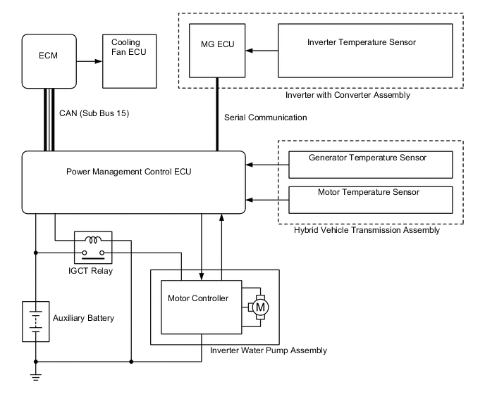
The power management control ECU receives signals from the temperature sensors for the inverter with converter assembly, generator temperature sensor and motor temperature sensor. Then, the power management control ECU actuates the inverter water pump assembly over 4 levels using duty cycle control, in order to cool the inverter with converter assembly, generator (MG1) and motor (MG2).
-
When the HV coolant temperature rises above a certain level, the power management control ECU transmits a radiator fan drive request signal to the ECM. In response to that signal, the ECM actuates the radiator fan to restrain the HV coolant temperature increase, ensuring the cooling of the inverter with converter assembly, generator (MG1) and motor (MG2).
-
The MG ECU converts the temperature sensor signals into digital signals, and transmits them to the power management control ECU via serial communication.
-
-