ENGINE UNIT
-
CONSTRUCTION
-
An aluminum cylinder block sub-assembly with a 7 mm (0.276 in.) distance between the cylinder bores is used to achieve a compact and lightweight configuration.
-
Water passages have been provided between the cylinder bores. By allowing the engine coolant to flow between the cylinder bores, this construction enables the temperature of the cylinder walls to be kept uniform.
-
The liners are a spiny-type, which have been manufactured so that their casting exteriors form large irregular surfaces in order to enhance the adhesion between the liners and the aluminum cylinder block sub-assembly. The enhanced adhesion helps heat dissipation, resulting in a lower overall temperature and reduced heat deformation of the cylinder bores.
-
A larger breather hole is provided in the journal wall. As a result, friction is reduced and output performance is improved.
-
The basic structure of the engine, such as the thickness of the cylinder bore walls, the depth of the water jackets, and the cylinder block ribs has been optimized, reducing deviation from circularity of the cylinder bore, and thus reducing the friction, improving fuel consumption.
-
The angle of the bore cross hatching, the polishing on the cylinder liner surface, is at an angle of 30°, thus improving the oil retention of the interior of the cylinder bore. This reduces the friction between the cylinder bore and the piston, improving fuel consumption.
-
The shape of the ribs, and the positioning and shape of the knock control sensor have been optimized, thus improving control of knocking.
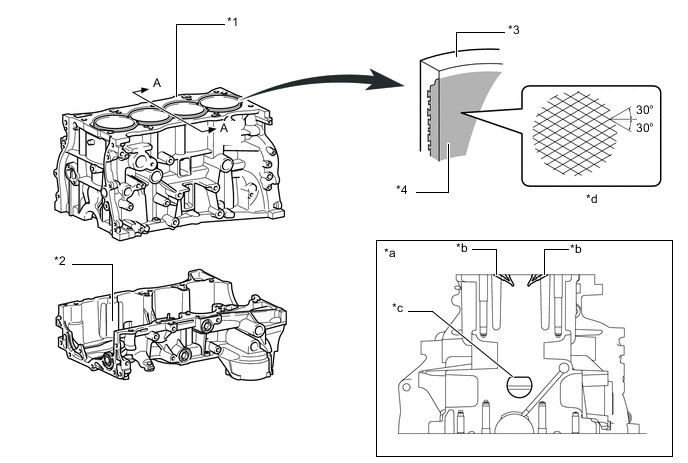
*1 Cylinder Block Sub-assembly *2 Stiffening Crankcase Assembly *3 Cylinder Bore *4 Spiny-type Liner (Irregularly Shaped Outer Casting Surface of Liner) *a A - A Cross Section *b Water Passage *c Larger Breather Hole *d Bore Cross Hatch -
Through the use of an offset crankshaft, the centerline of the bores is shifted 10 mm (0.39 in.) towards the exhaust side in relation to the centerline of the crankshaft. Thus, the side force to the cylinder wall is reduced when the maximum pressure is applied. This contributes to fuel economy.
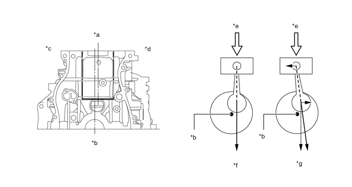
*a Bore Centerline *b Crankshaft Center *c Intake Side *d Exhaust Side *e Maximum Pressure *f Offset Crankshaft *g Non-offset Crankshaft - - -
A shallow bottom water jacket is used. The resulting reduction in the volume of the engine coolant improves warm-up performance, which contributes to improved fuel economy.
-
A cylinder block water jacket spacer utilizing resin with excellent heat resistance and shaping precision is used.
-
A cylinder block water jacket spacer is provided in the water jacket of the cylinder block sub-assembly.
-
The cylinder block water jacket spacer suppresses the water flow in the bottom of the water jackets, guides the coolant in the upper area of the water jacket, and ensures uniform temperature distribution. As a result, the viscosity of the engine oil that acts as a lubricant between the bore walls and the pistons can be lowered, thus reducing friction. Additionally, the coolant intake at the left side of the No. 1 cylinder bore is covered, thus preventing the No.1 cylinder bore from excessive cooling.
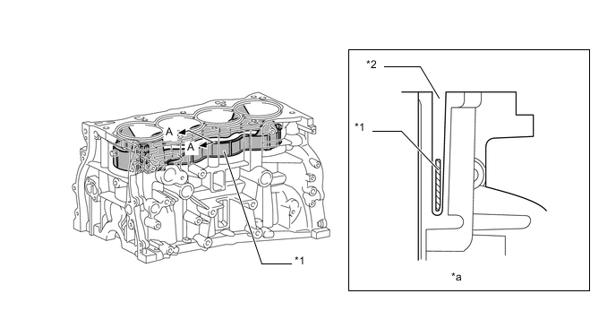
*1 Cylinder Block Water Jacket Spacer *2 Water Jacket *a A - A Cross Section - -
-