AIR CONDITIONING SYSTEM
-
CONSTRUCTION
-
The air conditioning unit consists of the No. 1 cooler evaporator sub-assembly, No. 1 heater radiator unit sub-assembly, servo motors, evaporator temperature sensor (No. 1 cooler thermistor) and blower with fan motor sub-assembly.
-
The No. 1 cooler evaporator sub-assembly and No. 1 heater radiator unit sub-assembly are mounted transversely to achieve a compact and lightweight form.
-
A bus connector is used in the wire harness connection, which connects the servo motor to the air conditioning amplifier assembly.
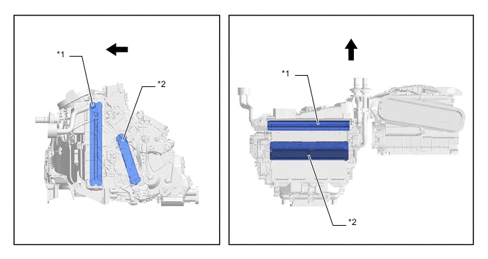
*1 No. 1 Cooler Evaporator Sub-assembly *2 No. 1 Heater Radiator Unit Sub-assembly 
Front - - -
An inside-and-outside dual air layer type air conditioning unit is used. This type of air conditioning unit introduces outside air to the upper side and circulates inside air to the lower side, thus achieving antifogging performance and ventilation loss reduction.
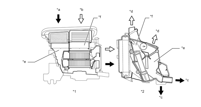
*1 Blower with Fan Motor Sub-assembly *2 Air Conditioning Radiator Assembly *a Introduces Inside Air *b Introduces Outside Air *c Blows Inside Air *d Blows Outside Air *e Lower Layer *f Upper Layer -
Sliding doors are used for the air mix control doors (upper layer side and lower layer side) and mode control door (upper layer side), thus making the air conditioning radiator assembly more compact.
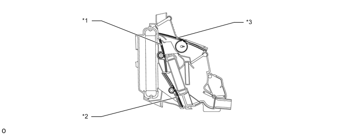
*1 Air Mix Control Door (Upper Layer Side) *2 Air Mix Control Door (Upper Layer Side) *3 Mode Control Door (Upper Layer Side) - - -
A mode control door (DEF) exclusive to the defroster is installed in the air conditioning radiator assembly, thus making it possible for air to be blown from the defroster nozzle even in bi-level mode.
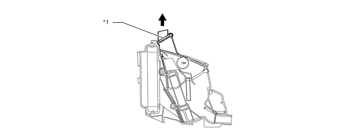
*1 Mode Control Door (DEF) - - To Defroster Nozzle - -
-