VARIABLE GEAR RATIO STEERING SYSTEM
-
CONSTRUCTION
-
The steering actuator assembly consists of a housing, a motor, a reduction mechanism, an output shaft, and a lock mechanism.
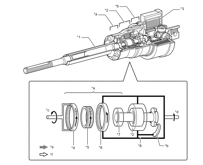
*1 Output Shaft *2 Motor *3 Spiral Cable *4 Driven Gear *5 Flexible Gear *6 Stator Gear *7 Wave Generator *8 Housing *a Reduction Mechanism *b Lock Mechanism *c Output Shaft Rotational Direction *d Steering Wheel Rotational Direction *e Motor Rotational Direction *f VGRS Rotational Angle -
Motor
-
A compact, high power output, and low noise brushless type motor is used. This motor is enclosed in the housing.
-
This motor mainly consists of a magnet, a coil, and a motor shaft. The motor shaft is coupled to the wave generator of the reduction mechanism in order to transmit the rotational movement of the motor to the reduction mechanism.
-
This motor, which is controlled by the signal from the front steering control ECU, rotates either clockwise or counterclockwise, depending on the direction in which the steering wheel assembly is turned.
-
The rotation angle sensor detects the rotational direction and rotational angle of the motor.
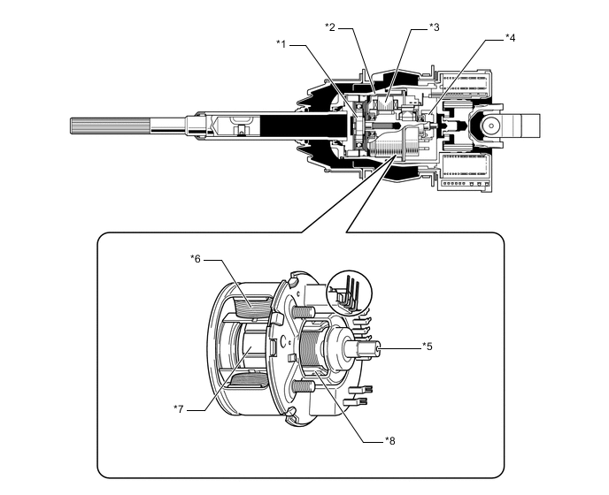
*1 Reduction Mechanism *2 Housing *3 Motor *4 Lock Mechanism *5 Motor Shaft *6 Coil *7 Magnet *8 Rotation Angle Sensor
-
-
Reduction Mechanism
-
The reduction mechanism uses strain wave gearing, which is compact and highly accurate, and creates a large reduction gear ratio (1:50) using a small number of components.
-
This reduction mechanism consists of a driven gear, a stator gear, a flexible gear, and a wave generator.
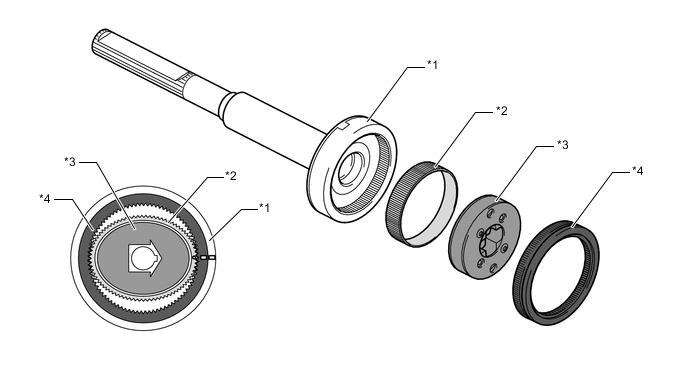
*1 Driven Gear *2 Flexible Gear *3 Wave Generator *4 Stator Gear Construction of Reduction Mechanism Item Construction Stator Gear (Input)
-
Has a rigid body and a ring shape, and contains 102 teeth along the inner circumference.
-
Positioned parallel to the driven gear.
-
Coupled to the housing of the steering actuator assembly.
Driven Gear (Output)
-
Has a rigid body and a ring shape, and contains 100 teeth along the inner circumference.
-
Positioned parallel to the stator gear.
-
Coupled to the output shaft of the steering actuator assembly.
Flexible Gear
-
Has a flexible metal body that forms a belt shape and contains 100 teeth along the outer circumference.
-
Located outside of the wave generator, and positioned in such a way that its gear teeth are meshed with the inside of both the stator gear and the driven gear.
Wave Generator
-
Consists of an oval-shaped cam and a ball bearing that is fitted around the cam.
-
Coupled to the motor shaft of the motor and rotates inside the flexible gear while pushing the flexible gear against the stator gear and the driven gear.
-
-
-
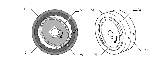
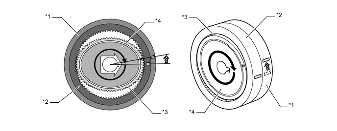
Lock Mechanism
-
This system contains a lock mechanism that mechanically locks the motor so that the motor will not rotate if a malfunction occurs. Along with this, the housing and the output shaft are integrated.
-
The lock mechanism is mounted on the motor. The mechanism consists primarily of a lock holder that is secured to the motor shaft, a lock lever that is mounted on the housing, and a lock solenoid that operates the lock lever.
-
When the lock mechanism is activated, the front steering control ECU turns off the current to the lock solenoid, and the return spring pushes the lock lever against the lock holder. Then, the lock lever meshes with the groove in the lock holder in order to mechanically lock the movement of the motor. When the lock is disengaged, the front steering control ECU turns on the current to the lock solenoid, thus disengaging the lock lever and the lock holder and freeing the movement of the motor.

*1 Lock Lever *2 Lock Holder *3 Motor Shaft *4 Lock Solenoid *a Unlock State (Lock Solenoid On) *b Lock State (Lock Solenoid Off)
-
-
-
OPERATION
-
Reduction Mechanism Operation
-
The flexible gear is fitted inside the driven gear and stator gear as illustrated. Furthermore, the wave generator is fitted inside the flexible gear. The rotational movement of the wave generator causes the flexible gear to become deformed into an oval shape. The teeth at the major axis of the oval shape mesh with the teeth of the driven gear and stator gear, and the teeth at the minor axis are disengaged.
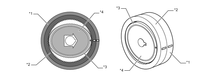
*1 Driven Gear *2 Stator Gear *3 Flexible Gear *4 Wave Generator -
When the stator gear is fixed and the wave generator rotates clockwise, the flexible gear undergoes an elastic deformation. This causes the meshed areas between the flexible gear, driven gear and stator gear to move consecutively.
*1 Driven Gear *2 Stator Gear *3 Flexible Gear *4 Wave Generator -
When the wave generator makes 1 rotation, the flexible gear moves counterclockwise by 2 teeth because it has 2 fewer teeth than the stator gear. The driven gear and the flexible gear have the same number of teeth, so their rotational movements are identical. Therefore, the driven gear (output) moves by 2 teeth.
*1 Driven Gear *2 Stator Gear *3 Flexible Gear *4 Wave Generator 
Stator gear moves clockwise by 2 teeth. - -
-
-
System Operation
-
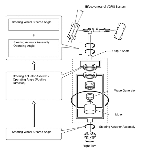
This system rotates the steering actuator assembly in the positive direction in the low speed range (in which a reduction in the steering wheel assembly operating angle is desired) or in the medium speed range (in which an agile vehicle response is desired).
-
When the driver turns the steering wheel assembly clockwise, the front steering control ECU rotates the motor in the steering actuator assembly counterclockwise.
-
Then, the rotational movement of the motor is input into the reduction mechanism by way of the wave generator. The rotational movement is reduced to a 1:50 gear ratio, and is output from the output shaft in the clockwise direction. This operating angle of the steering actuator assembly is thus added to the angle in which the steering wheel assembly is steered by the driver. Therefore, the output shaft rotates further clockwise than the actual steered angle of the steering wheel assembly by the operation of the steering actuator assembly. As a result, the front wheels turn more to the right.
-
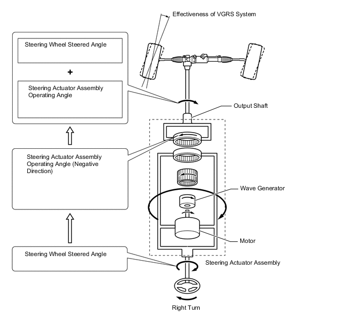
This system rotates the steering actuator assembly in the negative direction in the high speed range (in which an over-sensitive movement response of the vehicle is not desired).
-
When the driver turns the steering wheel assembly clockwise, the front steering control ECU rotates the motor in the steering actuator assembly clockwise.
-
Then, the rotational movement of the motor is input into the reduction mechanism by way of the wave generator. The rotational movement is reduced to a 1:50 gear ratio, and is output from the output shaft in the counterclockwise direction. This operating angle of the steering actuator assembly is thus subtracted from the angle in which the steering wheel assembly is steered by the driver. Therefore, the output shaft does not rotate as far clockwise as the actual steered angle of the steering wheel assembly by the operation of the steering actuator assembly. As a result, the front wheels turn less to the right.
-
-