VARIABLE GEAR RATIO STEERING SYSTEM
-
FUNCTION OF MAIN COMPONENTS
Component Function Front Steering Control ECU Operates the motor by calculating the operating angle of the steering actuator assembly based on the signals from the steering sensor and each ECU. Steering Actuator Assembly Motor Rotates to create the operating angle of the steering actuator assembly upon receiving the signals from the front steering control ECU. Reduction Mechanism Uses a strain wave gear type reduction mechanism to reduce the rotation of the motor to the 1:50 ratio. Lock Solenoid Locks the motor shaft so that the motor will not rotate in case of a system malfunction. Rotation Angle Sensor Outputs the rotational angle of the motor to the front steering control ECU. Steering Sensor Detects the steering direction and angle of the steering wheel assembly. Power Steering ECU Assembly Sends the steering assist signal to the steering control ECU. Brake Actuator Assembly Skid Control ECU
-
Outputs the vehicle speed signal.
-
Requests the steering control (EPS system and VGRS system) during cooperative control.
ECM Sends information about the drive mode selected by the drive mode select to each ECU. Combination Switch Assembly Drive Mode Select Switches the driving mode. Combination Meter Assembly Multi-information Display Displays the warning message to inform the driver of a malfunction in the system. Master Warning Light The master warning light turns on to alert the driver when the front steering control ECU detects a malfunction in the system. Multi Buzzer Sounds to warn the driver of a malfunction in the system. -
-
SYSTEM CONTROL
-
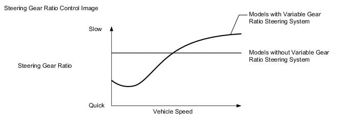
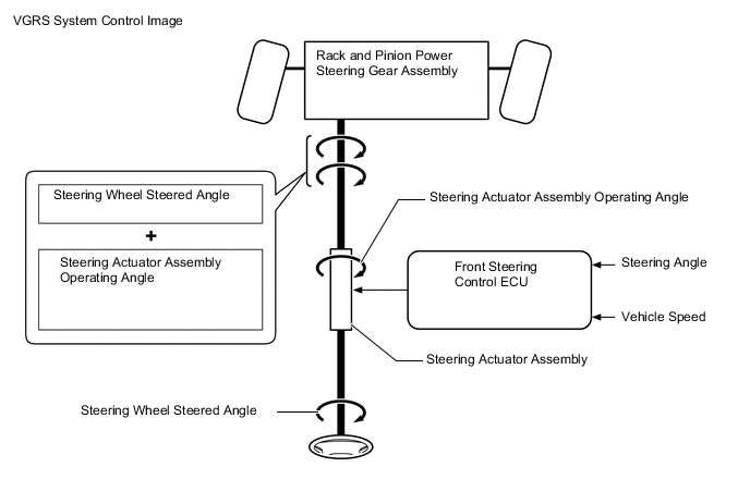
The front steering control ECU calculates the steering actuator assembly target operating angle in accordance with the steering sensor signal and vehicle speed signal.
-
The front steering control ECU controls the turning angle of the front wheels by adding the operating angle of the steering actuator assembly to the angle to which the steering wheel assembly is steered by the driver. As a result, the steering gear ratio fluctuates depending on the driving conditions. Thus, excellent steering feel and vehicle stability are achieved, regardless of the vehicle speed, from the low- to high-speed ranges.
-
The front steering control ECU calculates the steering speed based on the steering sensor signal and corrects the steering actuator assembly operating angle, thus improving steering response.
-
If a vehicle that is being driven straight ahead over a road surface with different friction coefficients brakes suddenly and causes the VSC to activate, the vehicle posture will become disrupted, thus requiring the driver to operate the steering wheel assembly. When this occurs, the skid control ECU (brake actuator assembly) transmits signals to the front steering control ECU. When the front steering control ECU receives these signals, it calculates the target operating angle for the steering actuator assembly based on the driver's steering angle and direction and the vehicle speed signal. Then, the VGRS system operates, reducing the driver's steering operation.
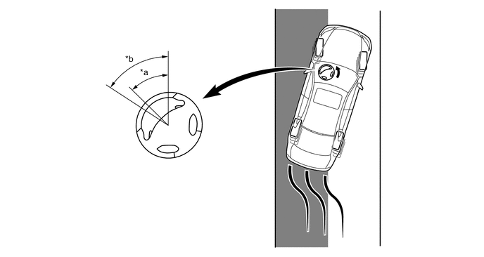
*a Driver's steering wheel angle under the control with a signal from the skid control ECU (brake actuator assembly) *b Driver's steering wheel angle under the control without a signal from the skid control ECU (brake actuator assembly) 
Slippery Surface - -
-
-
FAIL-SAFE
-
If a system malfunction occurs, the front steering control ECU turns off the lock solenoid of the lock mechanism and locks the motor in the steering actuator assembly.
-
-
DIAGNOSIS
-
If the front steering control ECU detects a malfunction in the VGRS system, it lights up the master warning light, indicates the warning message on the multi-information display and sounds the multi buzzer to alert the driver of the malfunction.
-
The front steering control ECU will also store a Diagnostic Trouble Code (DTC). The DTC can be accessed through the use of the Global TechStream (GTS). For details, refer to the Repair Manual.
-