AUTOMATIC TRANSMISSION SYSTEM
-
CONSTRUCTION
-
Models with 2GR-FKS Engine
-
The transmission valve body assembly consists of the upper and lower valve bodies and 9 shift solenoid valves.
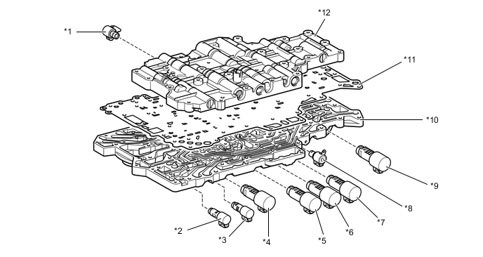
*1 Shift Solenoid Valve SR (Transmission 3-way Lock Up Solenoid Assembly) *2 Shift Solenoid Valve SLT (Line Pressure Control Solenoid Assembly) *3 Shift Solenoid Valve SLU (Lock Up Control Solenoid Assembly) *4 Shift Solenoid Valve SL1 *5 Shift Solenoid Valve SL5 *6 Shift Solenoid Valve SL4 *7 Shift Solenoid Valve SL3 *8 Shift Solenoid Valve SL (Transmission 3-way Lock Up Solenoid Assembly) *9 Shift Solenoid Valve SL2 *10 Lower Valve Body *11 Plate *12 Upper Valve Body Figure 1. Upper Valve Body
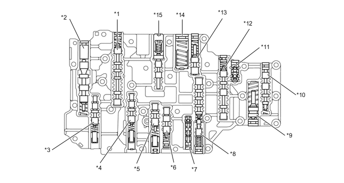
*1 Lock-up Relay Valve *2 Solenoid Regulator Valve *3 No. 1 Clutch Apply Control Valve *4 No. 1 B1 Apply Control Valve *5 No. 2 Clutch Apply Control Valve *6 C4 Relay Valve *7 Signal Check Valve *8 No. 2 Clutch Apply Relay Valve *9 C2 Damper *10 B2 Control Valve *11 B2 Check Valve *12 No. 1 Clutch Apply Relay Valve *13 Solenoid Modulator Valve *14 C1 Accumulator Valve *15 Lock-up Control Valve - - Figure 2. Lower Valve Body
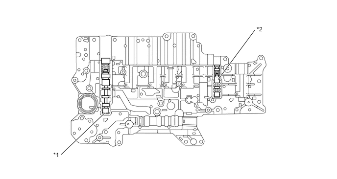
*1 Primary Regulator Valve *2 B2 Apply Control Valve
-
-
Models with 8AR-FTS Engine
-
The transmission valve body assembly consists of the upper and lower valve bodies and 9 shift solenoid valves.
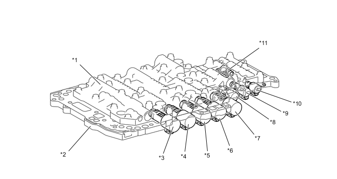
*1 Upper Valve Body *2 Lower Valve Body *3 Shift Solenoid Valve SL5 *4 Shift Solenoid Valve SL3 *5 Shift Solenoid Valve SL4 *6 Shift Solenoid Valve SL2 *7 Shift Solenoid Valve SL1 *8 Shift Solenoid Valve SLT *9 Shift Solenoid Valve SLU *10 Shift Solenoid Valve SC2 *11 Shift Solenoid Valve SC1 - - -
A lubrication relay valve is used to adjust the lubricant of the gears, bearings and friction materials during high and low loads. As a result, the lubrication flow amount during low loads is suppressed reducing transmission torque loss.
Figure 3. Upper Valve Body
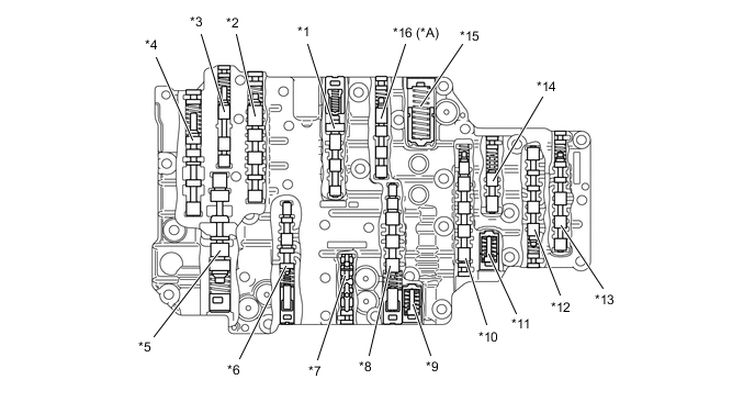
*A Models with Stop and Start System - - *1 Lock-up Control Valve *2 Lock-up Relay Valve *3 Lubrication Relay Valve *4 Secondary Regulator Valve *5 Primary Regulator Valve *6 No. 1 Clutch Apply Control Valve *7 Signal Check Valve *8 No. 2 Clutch Apply Control Valve *9 C2 Damper *10 Sequence Valve *11 C1 Damper *12 C3-B2 Control Valve *13 Solenoid Relay Valve *14 Solenoid Modulator Valve *15 C1 Accumulator *16 C1 Apply Relay Valve
-
-