AUTOMATIC TRANSMISSION SYSTEM
-
FUNCTION OF MAIN COMPONENTS
Component Function ATF Warmer (Transmission Oil Cooler)
-
Warms up the ATF quickly.
-
Keeps the ATF temperature higher (within limits).
Torque Converter Assembly
-
Transmits the engine power to the transmission.
-
Increases engine torque.
Oil Pump Assembly Provides oil pressure necessary for the transmission operation. No. 1 Clutch (C1) Connects the front planetary ring gear and rear sun gear. No. 2 Clutch (C2) Connects the intermediate shaft and rear planetary carrier. No. 3 Clutch (C3) Connects the front planetary ring gear and middle sun gear. No. 4 Clutch (C4) Connects the front planetary carrier and middle sun gear. No. 1 Brake (B1) Prevents the middle sun gear from turning either clockwise or counterclockwise. No. 2 Brake (B2) Prevents the rear planetary carrier from turning either clockwise or counterclockwise. No. 1 1-way Clutch (F1) Prevents the rear planetary carrier from turning counterclockwise. Planetary Gears Change the power transmission route in accordance with clutch and brake operation, and increase or decrease output shaft revolution accordingly. Shift Solenoid Valve SL1 Controls No. 1 clutch (C1) pressure. Shift Solenoid Valve SL2 Controls No. 2 clutch (C2) pressure. Shift Solenoid Valve SL3 Controls No. 3 clutch (C3) pressure. Shift Solenoid Valve SL4 Controls No. 4 clutch (C4) pressure. Shift Solenoid Valve SL5 Controls No. 1 brake (B1) pressure. Shift Solenoid Valve SLU (Lock Up Control SolenoidAssembly)
-
Controls lock-up clutch pressure.
-
Controls No. 2 brake (B2) pressure.
Shift Solenoid Valve SLT (Line Pressure ControlSolenoid Assembly) Controls line pressure. Shift Solenoid Valve SL (Transmission 3-way Lock UpSolenoid Assembly)*1
-
Switches the lock-up relay valve.
-
Switches the reverse control valve.
Shift Solenoid Valve SR (Transmission 3-way Lock UpSolenoid Assembly)*1
-
Switches the clutch control valve.
-
Switches the sequence control valve.
Shift Solenoid Valve SC1 (Transmission 3-way Lock Up Solenoid Assembly)*2 Switches the C3-B2 apply control valve, working together with the shift solenoid valve SC2 (transmission 3-way lock up solenoid assembly). Shift Solenoid Valve SC2 (Transmission 3-way Lock Up Solenoid Assembly)*2
-
Switches the C3-B2 apply control valve, working together with the shift solenoid valve SC1 (transmission 3-way lock up solenoid assembly).
-
Switches the solenoid relay valve.
ATF Temperature Sensor Detects the ATF temperature. ATF Pressure Switch Monitors output fluid pressure of each shift solenoid valve. Transmission Revolution Sensor (NT) Detects the input speed of the transmission. Transmission Revolution Sensor (NC3) Detects the speed of the middle sun gear input drum. Transmission Revolution Sensor (SP2) Detects the output speed of the transmission. Yawrate Sensor
-
Detects the vehicle's longitudinal and lateral acceleration.
-
Detects the vehicle's yaw rate.
Park/Neutral Position Switch Assembly Detects the shift lever position (P, R, N, D). Transmission Control Switch
-
Detects that the shift lever is in M.
-
Detects the driver's upshift and downshift operations when the shift lever is in M.
Shift Paddle Switch (Transmission Shift Switch Assembly) Detects the driver's upshift and downshift operations when the shift lever is in D or M. Combination Switch Assembly Drive Mode Select Selects the drive mode (ECO, NORMAL, SPORT*3, SPORT S*4 or SPORT S+*3). SNOW Switch*5 Selects the SNOW mode. Combination Meter Assembly MIL Illuminates or blinks to inform the driver when the ECM detects a malfunction. Multi-information Display
-
Displays the shift lever position.
-
Displays the shift range.
-
Displays the gear position.
-
Displays the drive mode.
-
Displays the message when the ATF is at a high temperature.
Multi Buzzer Sounds when downshift operation is rejected in M mode. TCM*1
-
Controls each shift solenoid valve in response to a signal from each sensor and switch.
-
Controls each shift solenoid valve in response to a signal from each sensor and switch.
ECM*1 Controls engine output in response to a signal from the TCM. ECM*2
-
Controls each shift solenoid valve and engine output in response to a signal from each sensor and switch.
-
When the ECM detects a malfunction, it makes a diagnosis and memorizes the failed section.
Skid Control ECU Sends the information about the operation conditions of the brake control system to the ECM. Driving Support ECU Assembly *6 Sends the information about the operation conditions of the dynamic radar cruisecontrol system to the ECM. Tech Tips
*1: Models with 2GR-FSE Engine
*2: Models with 8AR-FTS Engine
*3: Except F SPORT
*4: For F SPORT
*5: Except Models for G.C.C. Countries
*6: Models with Dynamic Radar Cruise Control System
-
-
SYSTEM CONTROL
Electronic Control of Automatic Transmission Control Function Shift Timing Control The TCM*1 or ECM*2 sends current to each shift solenoid valves based on signals from various sensors in order to shift the gears. Line Pressure Control Actuates the shift solenoid valve SLT (line pressure control solenoid assembly) to control the line pressure in accordance with information from the TCM*1 or ECM*2 and the operating conditions of the transmission. Clutch Pressure Optimal Control The shift solenoid valves SL1, SL2, SL3, SL4, SL5, SLT (line pressure control solenoid assembly) and SLU (lock up control solenoid assembly) minutely control theclutch pressure in accordance with the engine output and driving conditions of the transmission. Clutch to Clutch Pressure Control Controls the pressure that is applied directly to B1 brake and each clutches by actuating the shift solenoid valves SL1, SL2, SL3, SL4 and SL5 in accordance with the TCM signals. Powertrain Cooperative Control Controls both the shift control and engine output control in an integrated way, thus achieving excellent shift characteristics and driveability. Coast Downshift Control To prevent engine speed from decreasing and thereby maintain fuel cut, the TCM*1 or ECM*2 performs downshifts before fuel cut ends. Lock-up Timing Control The TCM*1 or ECM*2 sends current to the shift solenoid valve SLU (lock up control solenoid assembly) based on signals from various sensors and engages or disengages the lock-up clutch. Flex Lock-up Clutch Control Controls the shift solenoid valve SLU (lock up control solenoid assembly), provides an intermediate mode for when the lock-up clutch is between on and off, and increases the operating range of the lock-up clutch to improve fuel economy. Multi-mode Transmission
-
The TCM*1 or ECM*2 appropriately controls the automatic transmission in accordance with the shift range or gear range selected using the shift lever or shift paddle switch (transmission shift switch assembly) while the shift lever is in M.
-
An improvement in manual operation response and driveability has been achieved by the gear hold control, high response upshift control and blipping downshift control.
-
When the shift lever is in D, the driver can select a desired shift range using the shift paddle switch (transmission shift switch assembly).
Artificial Intelligence Shift Control (AI-shift Control) Based on the signals from various sensors, the TCM*1 or ECM*2 determines the road conditions and the intention of the driver. Thus, an appropriate shift pattern is automatically determined, thus improving driveability. 2nd Gear Start-off and Stop Control When the engine idling speed is high while the engine is warming up and the road surface is slippery, 2nd gear start-off and stop control for low-friction roads is automatically used in order to enhance control of driving force using the accelerator. Differential Protection Control
-
When there is a large rotation difference between the left and right wheels, shifting will be prevented to protect the differential.
-
The TCM*1 or ECM*2 regulates engine torque down control to protect the differential when in 1st gear range.
ATF High Temperature Control When the ATF is at a high temperature, normal shifting characteristics will be changed to shifting characteristics which actively utilize the low gear range to prevent the oil temperature from rising further. *1: Models with 2GR-FSE Engine
*2: Models with 8AR-FTS Engine
-
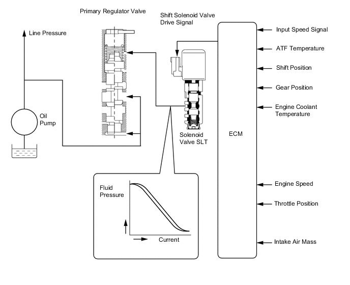
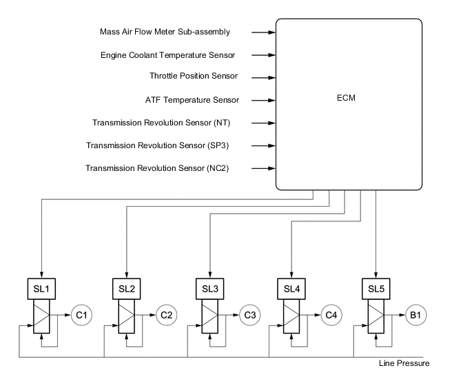
Line Pressure Control
-
The line pressure is controlled by using shift solenoid valve SLT (line pressure control solenoid assembly). Through the use of shift solenoid valve SLT (line pressure control solenoid assembly), the line pressure is optimally controlled in accordance with the engine torque information, as well as with the internal operating conditions of the torque converter and the transmission. Accordingly, the line pressure can be accurately controlled in accordance with the engine output, traveling condition, and the ATF temperature, thusr ealizing smooth shift characteristics and optimizing the workload of the oil pump.
Figure 1. Models with 2GR-FSE Engine
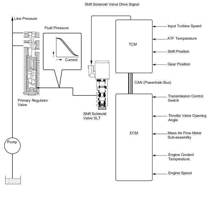
Figure 2. Models with 8AR-FTS Engine
-
-
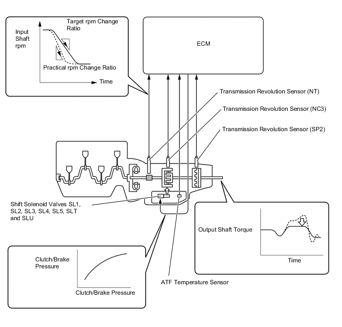
Clutch Pressure Optimal Control
-
The TCM*1 or ECM*2 monitors the signals from various types of sensors, such as the transmission revolution sensor (NT) and transmission revolution sensor (NC3), allowing shift solenoid valve SL1, SL2, SL3, SL4, SL5, SLT (line pressure control solenoid assembly) and shift solenoid valve SLU (lock up control solenoid assembly) to minutely control the clutch pressure in accordance with engine output and driving conditions. As a result, smooth shift characteristics are achieved.
Tech Tips
*1: Models with 2GR-FSE Engine
*2: Models with 8AR-FTS Engine
Figure 3. Models with 2GR-FSE Engine
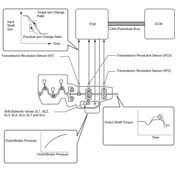
Figure 4. Models with 8AR-FTS Engine
-
-
Clutch to Clutch Pressure Control
-
Clutch to clutch pressure control is used for shift control. As a result, shift control in the 2nd gear or above is possible without using the 1-way clutch, and the automatic transmission has been made lightweight and compact.
-
Using the fluid pressure circuit, which enables the clutches and brakes (C1, C2, C3, C4 and B1) to be controlled independently, and the high flow SL1, SL2, SL3, SL4 and SL5 shift solenoid valves, which directly control the line pressure, the TCM*1 or ECM*2 controls each clutch and brake accordingly with the optimum fluid pressures and timings in accordance with the information transmitted by the sensors, and then shifts the gears. As a result, highly responsive and excellent shift characteristics have been achieved.
Tech Tips
*1: Models with 2GR-FSE Engine
*2: Models with 8AR-FTS Engine
Figure 5. Models with 2GR-FSE Engine
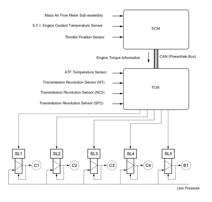
Figure 6. Models with 8AR-FTS Engine
-
-
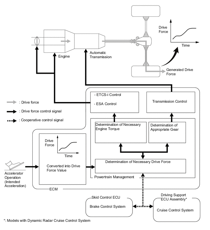
Driving Response and Acceleration Management System (DRAMS)
-
Driving Response and Acceleration Management System (DRAMS) is used for this vehicle. This system integrally controls the engine, transmission and other driving related controls. By integrally controlling the engine and automatic transmission using this system, quick response and a high quality driving feel in accordance with the driver's intentions are achieved, such as when accelerating or decelerating or during gear shifts.
Figure 7. Models with 2GR-FSE Engine
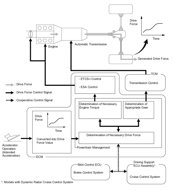
Figure 8. Models with 8AR-FTS Engine
-
Start Control
-
With DRAMS, engine torque will optimally be controlled in a real-time manner in accordance with speed ratios between engine speed and turbine speed so that finely controlled starting capability has been provided while balancing the "reduction of a feel of jump and suppression of tire slipping" and "smooth responsiveness" when starting.
-
-
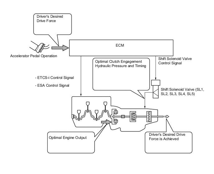
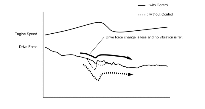
Transient Shifting Control
-
Through integrated control with Electronic Throttle Control System-intelligent (ETCS-i), Electronic Spark Advance (ESA), and electronic control of the engagement and release speed of clutch and brake hydraulic pressures, excellent response and shift shock reduction have been achieved.
Figure 9. Models with 2GR-FSE Engine
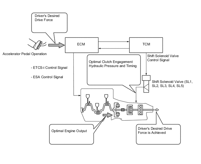
Figure 10. Models with 8AR-FTS Engine
-
Engine torque control used during gear shifts has been added to the cooperative control of the engine torque control and clutch hydraulic pressure control performed during gear shifts. This enhances gear engagement characteristics during gear shifts and achieves smooth gear changes.
-
-
-
Powertrain Cooperative Control
-
Integrated control of the powertrain (engine and transaxle) has created a new vehicle appeal. Powertrain cooperative control calculates the driver target motive force and target shift position in response to driver operations, the vehicle status and the road environment and performs precise control according to the engine control and ECT control conditions. As a result, driveability is improved.
-
The driver target motive force is set to achieve a long pleasant acceleration when an accelerator pedal operation performed to accelerate the vehicle is detected. Also, SPORT mode is used to provide an even sportier target motive force and target gear position according to driver accelerator pedal operation, enhancing the pleasant acceleration of the turbo engine and ensuring driving appeal.
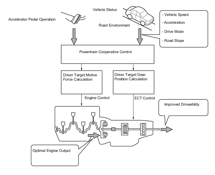
Figure 11. Acceleration when Accelerator Pedal Opening Angle is Maintained at Certain Amount
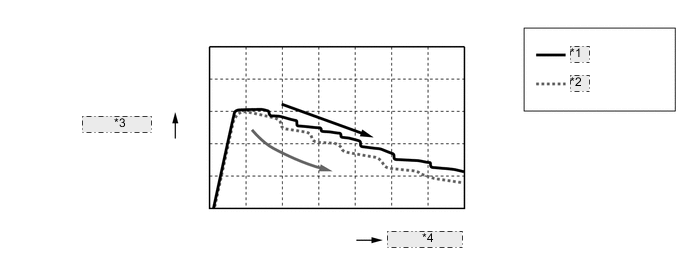
*1 with Control *2 without Control *3 Acceleration *4 Vehicle Speed
-
Linear feel improving control (Models with 2GR-FSE Engine)
-
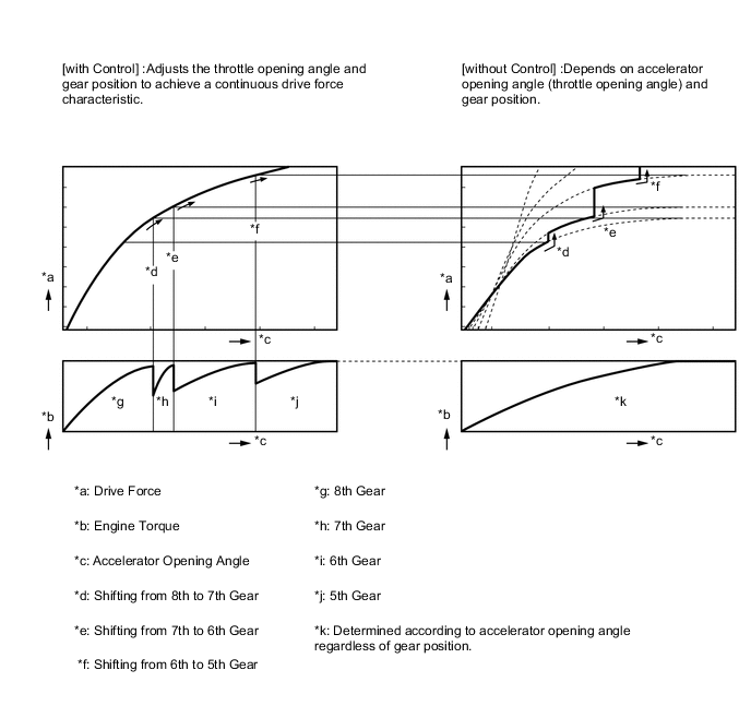
Conventionally, drive force was dependent on the accelerator pedal operation (throttle opening) and the gear position.
-
With the linear feel improving control, optimum engine torque (throttle opening) for the gear position is achieved, reducing the frequency of downshifting.
-
Continuous drive force has been achieved by reducing the variations in drive force when downshifting, improving controllability of the vehicle during accelerator pedal operation.
-
By reducing changes in the acceleration rate while the vehicle speed increases, a steady linear increase in vehicle speed that does not depend on the shift range has been achieved.
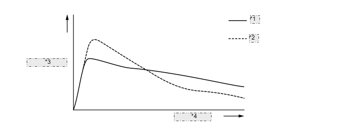
*1 with Control *2 without Control *3 Acceleration G *4 Vehicle Speed
-
-
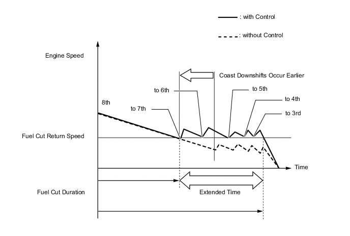
Coast Downshift Control
-
The TCM*1 or ECM*2 performs downshift control to prevent the engine speed from decreasing, thus keeping fuel cut control operating for as long as possible. In this way, the fuel economy is improved.
-
In this control, the transmission downshifts from 8th to 7th, 7th to 6th and then 6th to 5th before fuel cut control ends when the vehicle is decelerated in the 8th gear, so that fuel cut control continues operating. In addition, the TCM*1 or ECM*2 performs downshifting when the vehicle is decelerated both in the 6th and 7th gears.
Tech Tips
*1: Models with 2GR-FSE Engine
*2: Models with 8AR-FTS Engine
Figure 12. Models with 2GR-FSE Engine
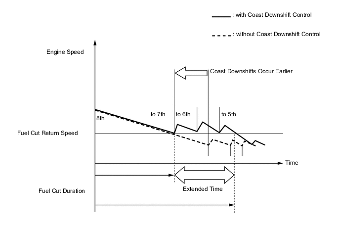
Figure 13. Models with 8AR-FTS Engine
-
-
Drive Mode Select Function
-
The drive mode can be selected by operating the drive mode select or SNOW switch.
-
The selected drive mode will be shown on the multi-information display in the combination meter assembly.
-
The drive characteristics of each drive mode are as follows:
Drive Mode Outline ECO Transmission characteristics which prioritize fuel-efficient driving are used to ensure low fuel consumption compared with that of NORMAL mode. NORMAL This drive mode provides optimum driveability. SPORT Mode*2
SPORT S Mode*3
The ECM improves acceleration performance and responsiveness by controlling the opening of the throttle and by changing the shift point of the transmission, thus achieving a sporty drive. SPORT S+ Mode*3 In addition to the control when in SPORT S mode, the suspension control system, brake control system and steering control system have been integrated to shift to SPORT mode, improved operability and stability have been aimed for even without losing comfort and a control which enables operation appropriate to the driver's intention is performed. SNOW*1 The TCM*4 or ECM*5 improves starting-off performance and acceleration performance on slippery road surfaces such as snow on which the wheels may spin by controlling to restrain drive force more than when in NORMAL mode. *1: Except Models for G.C.C. Countries
*2: Except F SPORT
*3: For F SPORT
*4: Models with 2GR-FSE Engine
*5: Models with 8AR-FTS Engine
Figure 14. Combination Switch Assembly (The illustration is a representative example.)
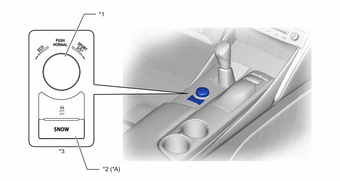
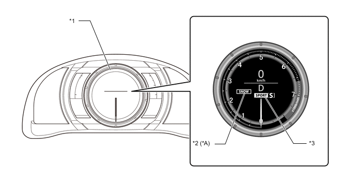
*A Except Models for G.C.C. Countries - - *1 Drive Mode Select *2 SNOW Switch *3 Combination Switch Assembly - - Figure 15. Optitron Meter
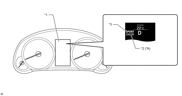
*A Except Models for G.C.C. Countries - - *1 Multi-Information Display *2 SNOW Mode Indicator Light *3 Drive Mode Indicator Light - - Figure 16. TFT LCD Meter
*A Except Models for G.C.C. Countries - - *1 Multi-Information Display *2 SNOW Mode Indicator Light *3 Drive Mode Indicator Light - -
-
-
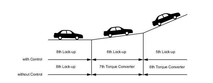
Hill-climbing Downshift Control
-
In hill-climbing situations that require drive force, downshifting control is performed based on slope information to improve driveability. When this occurs, lock-up continues in order to achieve a direct feeling in response to accelerator operations made by the driver.
-
-
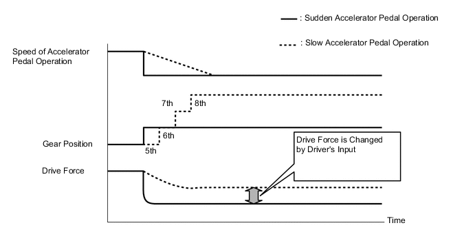
Deceleration Force Control
-
The TCM*1 or ECM*2 determines the gear position when the accelerator pedal is off (released completely) in accordance with the way the accelerator pedal is released (suddenly or slowly) during deceleration. In this way, unnecessary upshifts and downshifts are prevented when the accelerator pedal is off and subsequent smooth acceleration is ensured, matching the driver's intentions.
Tech Tips
*1: Models with 2GR-FSE Engine
*2: Models with 8AR-FTS Engine
-
-
-
Multi-mode Transmission
-
The driver can select the desired gear range by moving the shift lever to "+" (forward) or to "-" (backward) while the shift lever is in M. Also, the shift paddle switch (transmission shift switch assembly) can be used to change the gear range while the driver is holding the steering wheel. Thus, the driver is able to shift gears with a manual-like feel.
-
When the shift lever is in D, the driver can momentarily select a desired shift range by operating the shift paddle switch (transmission shift switch assembly). Automatic shifting will be reinstated under the following conditions:
- The vehicle has stopped.
- The driver continues to push the shift paddle switch (transmission shift switch assembly) in the "+" direction longer than 1 second.
- The driver depresses the accelerator pedal longer than a predetermined length of time.
-
When the vehicle is being driven at a prescribed speed or higher, any attempt to shift to a lower range by operating the shift lever will not be executed, in order to protect the automatic transmission. In this case, the ECM sounds the multi buzzer in the combination meter assembly twice to alert the driver.
Figure 17. Models with 2GR-FSE Engine
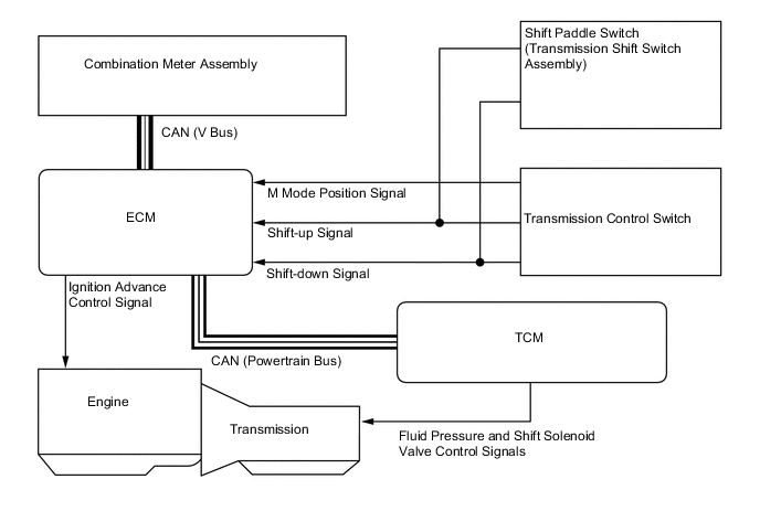
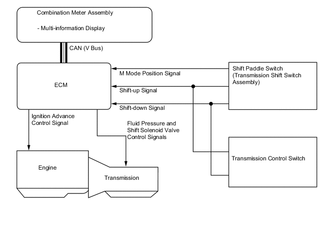
Figure 18. Models with 8AR-FTS Engine
-
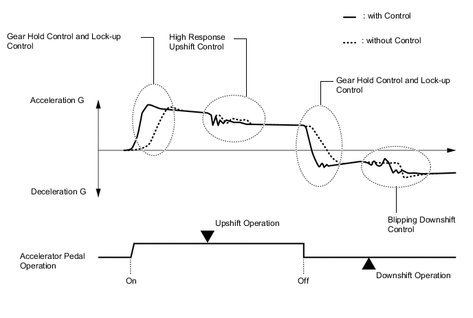
When the shift lever is in M, the gear hold control, lock-up control, high response upshift control and blipping downshift control are used in order to improve response in accordance with the driver's operation of the accelerator pedal, shift lever or transmission shift switch, and to improve gear shift feeling.
-
Gear Hold Control
-
Gear shifting will not be performed under gear hold control as long as the shift lever or shift paddle switch (transmission shift switch assembly) is not operated. This makes it possible to make efficient use of highest engine speeds. However, in the following cases, operation of gear hold control is limited.
Automatic shifting when the shift lever is in M
-
When the ATF or engine coolant temperature is low, gear shifting will be performed automatically.
-
When the ATF temperature is high, gear shifting will be performed automatically.
-
-
Lock-up Control
-
While the shift lever is in M, lock-up control operates from 2nd gear, transmitting the changes in engine power directly to the output shaft, the same way as with a manual transmission, and thus, direct response to the accelerator operation is achieved.
-
-
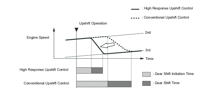
High Response Upshift Control
-
The high response upshift control achieves highly responsive upshift operation using the clutch to clutch pressure control, which regulates each clutch and brake quickly and precisely, and by the powertrain cooperative control, which optimally regulates engine torque during shifting.
-
-
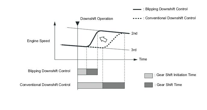
Blipping Downshift Control
-
The blipping downshift control regulates each clutch and brake using the clutch to clutch pressure control, allowing them to be engaged smoothly and disengaged quickly. In addition, fuel injection volume is increased and engine speed is boosted by the powertrain cooperative control, thus ensuring engine brake force. In this way, a smooth and quick downshift is achieved.
-
-
-
Control to Improve Feelings of Acceleration
-
Control is performed to improve the feeling of acceleration (suppress shocks) experienced when starting off or accelerating back up to speed, achieving smooth acceleration and drawing out the appeal of the vehicle.
-
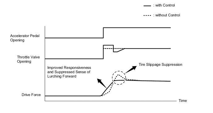
Throttle Control at Launch
-
The engine output is optimally controlled with Electronic Throttle Control System intelligent (ETCS-i) in real-time in accordance with the transient force from the torque converter when the vehicle is launched. This achieves a "suppressed sense of lurching forward", "tire slippage suppression" and "improved responsiveness", ensuring excellent launch performance.
-
-
-
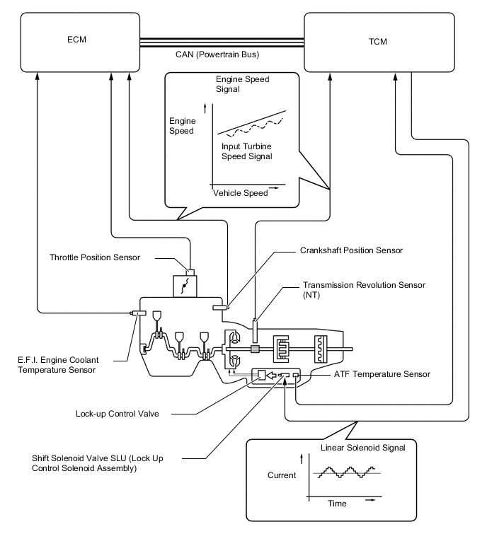
Lock-up Timing Control
-
Models with 2GR-FSE Engine
-
The TCM operates the lock-up timing control in order to improve the fuel economy performance.
Lock-up Timing Control Operation Gear Shift Lever Position M D, D8 D7 D6 1st X X X X 2nd ○* X X X 3rd ○* X X X 4th ○* X X X 5th ○* X X X 6th ○* ○ ○ ○ 7th ○* ○ ○ - 8th ○* ○ - - Tech Tips
○: Operates
X: Does not operate
*: Direct feel inprove control
-: Not applicable
-
-
Models with 8AR-FTS Engine
-
The ECM operates the lock-up timing control in order to improve the fuel economy performance.
-
A torque converter with a pendulum damper is used to expand the lock-up operating range. Also, this control can be performed even when the ATF temperature is low, contributing to improved fuel economy.
Lock-up Timing Control Operation Gear Shift Lever Position or Shift Range M D, D8 D7 D6 D5 D4 D3 1st X X X X X X X 2nd ○* X X X X X X 3rd ○* ○ ○ ○ ○ ○ ○ 4th ○* ○ ○ ○ ○ ○ - 5th ○* ○ ○ ○ ○ - - 6th ○* ○ ○ ○ - - - 7th ○* ○ ○ - - - - 8th ○* ○ - - - - - Tech Tips
○: Operates
X: Does not operate
-: Not applicable
*: Direct feel inprove control
-
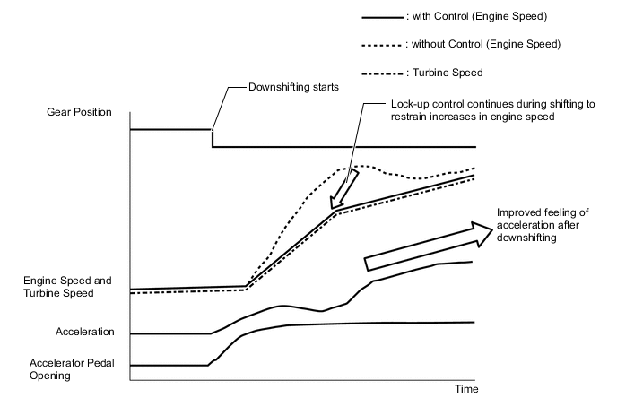
Downshift Lock-up Control
-
Downshift lock-up control maintains the lock-up condition even while downshifting. As a result, a sense of unity is provided between the feeling of the engine speed increasing and the feeling of acceleration after downshifting, producing a pleasant shifting experience. Also, lock-up continues in order to restrict unnecessary fuel consumption, contributing to improved fuel economy.
-
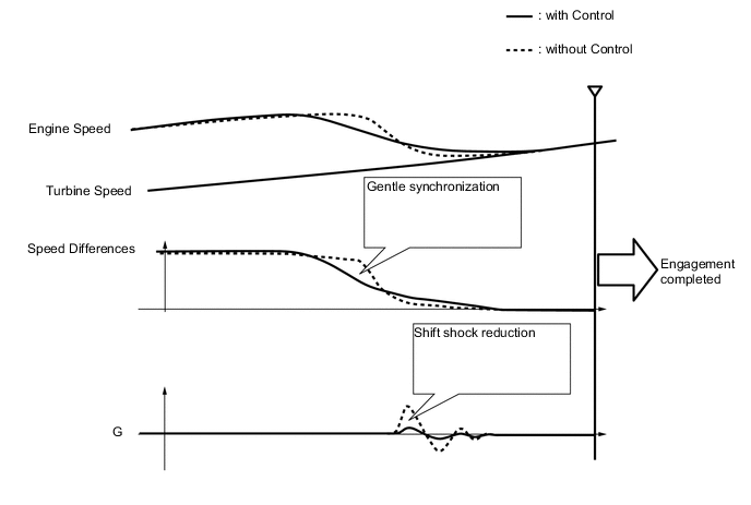
Lock-up Transition Control
-
When lock-up is engaged, the hydraulic pressure that engages the lock-up clutch is finely controlled to reduce shocks caused by shifting, allowing for smooth engagement even from low gear ranges.
-
-
-
Flex Lock-up Clutch Control
-
Models with 2GR-FSE Engine
-
In the low-to-mid-speed range, this flex lock-up clutch control regulates the shift solenoid valve SLU (lock up control solenoid assembly) to provide an intermediate mode between the on and off operations of the lock-up clutch in order to improve the energy transmitting efficiency. As a result, the operating range of the lock-up clutch has been increased and fuel economy has been improved.
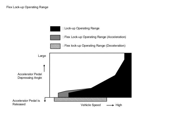
Flex Lock-up Clutch Control Operation Gear Shift Lever and Shift Range (Fixed Shift Range Mode) Position D, D8 D7 D6 D5 D4 1st X X X X X 2nd X X X X X 3rd X X X X X 4th ○ ○ ○ ○ ○ 5th ○* ○* ○* ○* - 6th ○* ○* ○* - - 7th ○* ○* - - - 8th ○* - - - - Tech Tips
*: Flex lock-up clutch control operates during deceleration.
○: Operates
X: Does not operate
-: Not applicable
-
-
Models with 8AR-FTS Engine
-
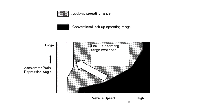
In the low-to-mid-speed range, this flex lock-up clutch control regulates the shift solenoid valve SLU to provide an intermediate mode between the on and off operations of the lock-up clutch in order to improve the energy transmitting efficiency. As a result, the operating range of the lock-up clutch has been increased and fuel economy has been improved.
-
For flex lock-up control, the lock-up range is expanded so that control only operates when decelerating. Also, expanding the flex lock-up range and allowing the control to operate when the ATF temperature is low contributes to enhanced fuel economy.
Flex Lock-up Clutch Control Operation (Deceleration) Gear Shift Lever Position or Shift Range D, D8 D7 D6 D5 D4 D3 1st X X X X X X 2nd X X X X X X 3rd * * * * * * 4th * * * * * - 5th * * * * - - 6th * * * - - - 7th * * - - - - 8th * - - - - - Tech Tips
*: Flex lock-up clutch control operates during deceleration.
-: Not applicable
X: Does not operate
-
-
-
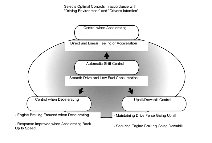
Artificial Intelligence Shift Control (AI-shift Control)
-
AI-shift control selects optimal controls in accordance with "driving environment" and the"driver's intention" based on the degree of accelerator opening, vehicle speed, brake signals, etc.
-
Smooth driving and low fuel consumption have been achieved while driving normally. A strong and linear feeling of acceleration has been provided when accelerating. A direct feeling of deceleration through engine braking and high fuel efficiency have been achieved when decelerating.
-
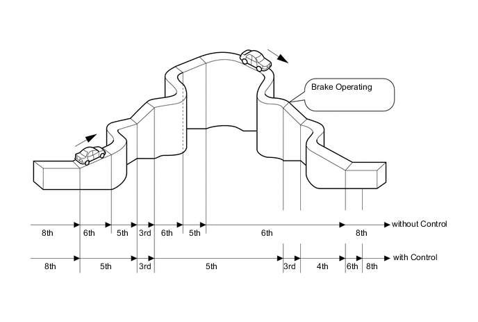
Uphill/Downhill Control
-
The TCM*1 or ECM*2 identifies the throttle valve opening angle, accelerator pedal opening angle and vehicle speed to determine whether the vehicle is being driven uphill or downhill. Unnecessary upshift is restrained to automatically achieve optimal drive force at all times while driving uphill. Downshift is automatically conducted to achieve optimal engine brake force, while driving downhill.Additionally, on models with the 8AR-FTS engine, the exclusive control improves responsiveness of the engine, achieving the optimal driving and deceleration force for driving on uphill and downhill slopes.
Tech Tips
*1: Models with 2GR-FSE Engine
*2: Models with 8AR-FTS Engine
-
-
Driver's Intention Support Control
-
The driver's intention support control is estimated based on the accelerator pedal operation, vehicle condition and a shift pattern that is well-suited to the driver is selected without operating the switch.
-
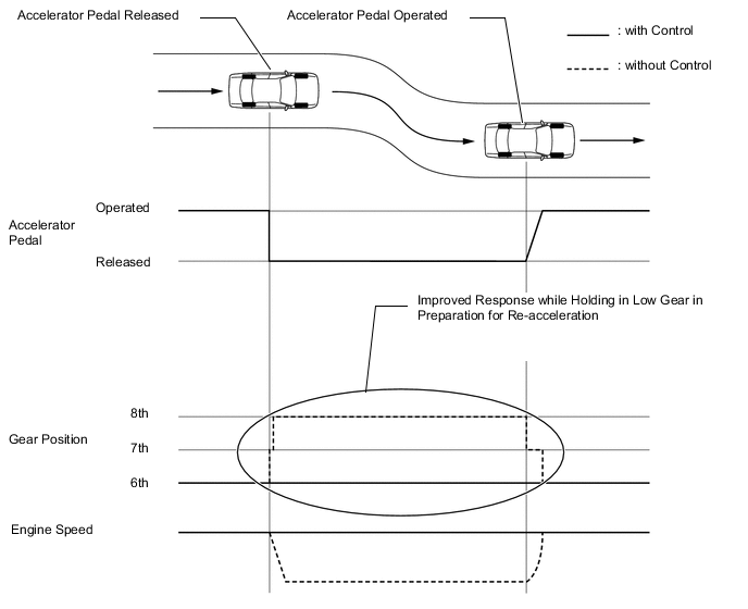
Sudden Accelerator Pedal Release Control
-
When the accelerator pedal is released suddenly, the transmission is kept in gear as long as possible, which improves engine braking force.
-
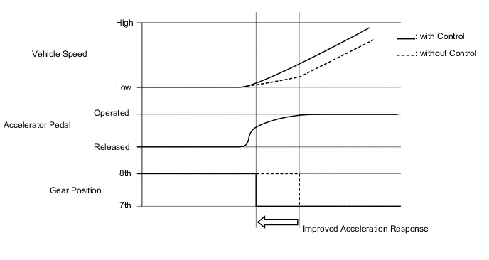
Sudden Accelerator Pedal Depress Control (Models with 2GR-FSE Engine)
-
When the accelerator pedal is depressed suddenly, downshifting occurs earlier providing for improved acceleration response.
-
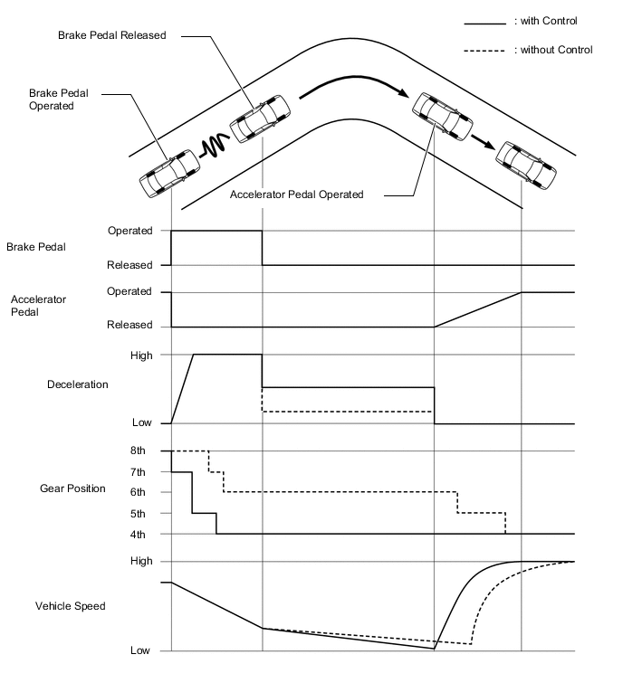
Downshifting control during hard braking
-
High engine braking force and good re-acceleration response have been achieved by actively downshifting during deceleration when hard braking is made.
-
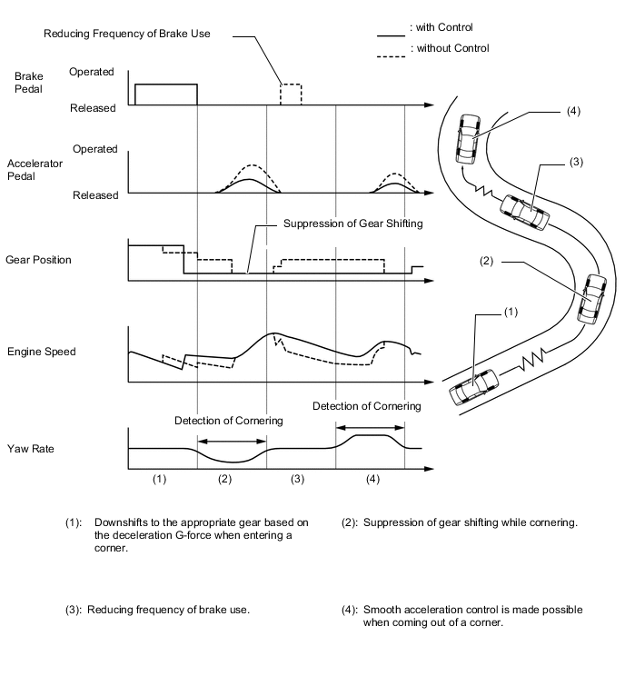
G AI-shift Control
-
When the vehicle enters a corner, this system assesses the overall vehicle condition based on signal from the G sensor signal and the driver's intention, and downshifts to the appropriate gear to obtain necessary driving force for coming out of a corner.
-
Controllability during cornering is ensured by suppressing gear shifting.
-
-
-
-
FAIL-SAFE
-
This function minimizes the loss of operability when an abnormality occurs in a sensor or solenoid. For details, refer to the Repair Manual.
-
-
DIAGNOSIS
-
When the TCM*1 or ECM*2 detects a malfunction, it makes a diagnosis and memorizes the failed section. Furthermore, the TCM*1 or ECM*2 illuminates or blinks the MIL in the combination meter assembly to inform the driver.
-
The TCM*1 or ECM*2 will also store the Diagnostic Trouble Codes (DTCs) of the malfunctions.
-
The DTCs can be read by connecting the Global TechStream (GTS) to the DLC3.
-
For details, refer to the Repair Manual.
Tech Tips
*1: Models with 2GR-FSE Engine
*2: Models with 8AR-FTS Engine
-