AUTOMATIC TRANSMISSION SYSTEM
Figure 1. RHD Models with 2GR-FKS Engine
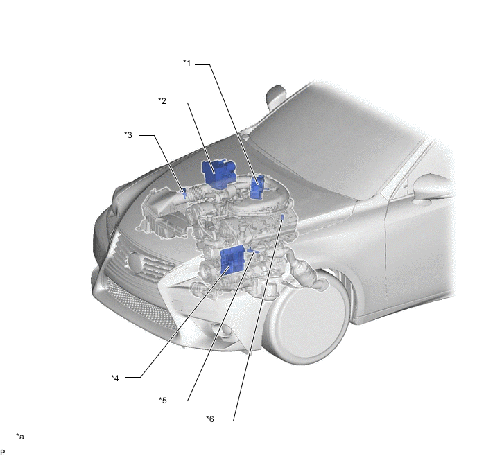
| *1 | Throttle Body with Motor Assembly
|
*2 | Brake Actuator Assembly
|
| *3 | Mass Air Flow Meter Sub-assembly | *4 | ECM |
| *5 | Crankshaft Position Sensor | *6 | E.F.I. Engine Coolant Temperature Sensor |
| *a | The illustrations shown are examples only. | - | - |
Figure 2. LHD Models with 2GR-FKS Engine
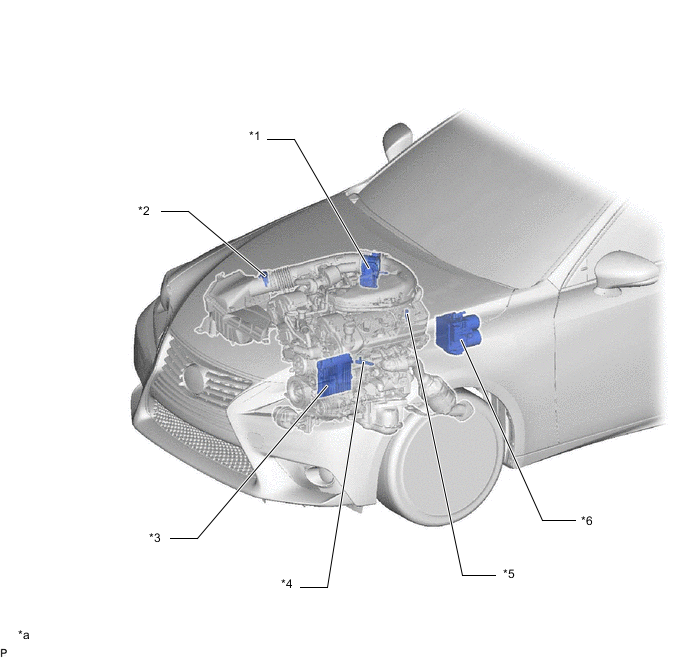
| *1 | Throttle Body with Motor Assembly
|
*2 | Mass Air Flow Meter Sub-assembly |
| *3 | ECM | *4 | Crankshaft Position Sensor |
| *5 | E.F.I. Engine Coolant Temperature Sensor | *6 | Brake Actuator Assembly
|
| *a | The illustrations shown are examples only. | - | - |
Figure 3. RHD Models with 8AR-FTS Engine
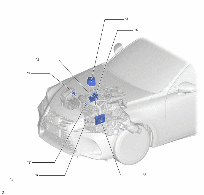
| *1 | Mass Air Flow Meter Sub-assembly | *2 | Throttle Body with Motor Assembly
|
| *3 | Brake Actuator Assembly
|
*4 | Ignition Coil Assembly |
| *5 | ECM | *6 | Crankshaft Position Sensor |
| *7 | E.F.I. Engine Coolant Temperature Sensor | - | - |
| *a | The illustrations shown are examples only. | - | - |
Figure 4. LHD Models with 8AR-FTS Engine
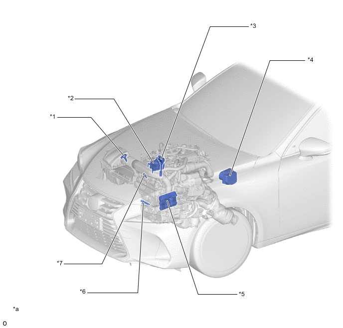
| *1 | Mass Air Flow Meter Sub-assembly | *2 | Throttle Body with Motor Assembly
|
| *3 | Ignition Coil Assembly | *4 | Brake Actuator Assembly
|
| *5 | ECM | *6 | Crankshaft Position Sensor |
| *7 | E.F.I. Engine Coolant Temperature Sensor | - | - |
| *a | The illustrations shown are examples only. | - | - |
Figure 5. Models with 2GR-FKS Engine
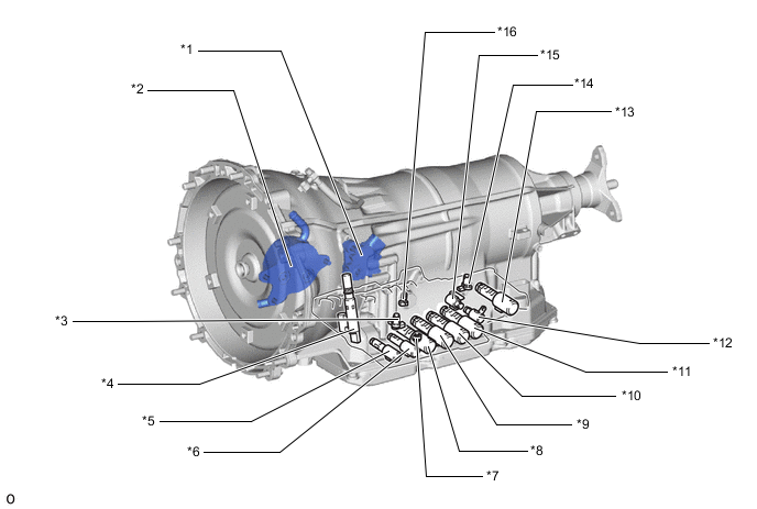
| *1 | Park/Neutral Position Switch Assembly | *2 | ATF Warmer (Transmission Oil Cooler) |
| *3 | Transmission Revolution sensor (NC3) | *4 | Transmission Revolution Sensor (NT) |
| *5 | Shift Solenoid Valve SLT (Line Pressure Control Solenoid Assembly) | *6 | Shift Solenoid Valve SLU (Lock Up Control Solenoid Assembly) |
| *7 | ATF Pressure Switch | *8 | Shift Solenoid Valve SL1 |
| *9 | Shift Solenoid Valve SL5 | *10 | Shift Solenoid Valve SL4 |
| *11 | Shift Solenoid Valve SL3 | *12 | Shift Solenoid Valve SL (Transmission 3-Way Lock Up Solenoid Assembly) |
| *13 | Shift Solenoid Valve SL2 | *14 | Transmission Revolution Sensor (SP2) |
| *15 | Shift Solenoid Valve SR | *16 | ATF Temperature Sensor |
Figure 6. Models with 8AR-FTS Engine
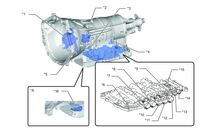
| *A | Models with Stop and Start System | - | - |
| *1 | ATF Warmer (Transmission Oil Cooler) | *2 | Park/Neutral Position Switch Assembly |
| *3 | Transmission Revolution Sensor (NC3) | *4 | Transmission Revolution Sensor (SP2) |
| *5 | Transmission Revolution Sensor (NT) | *6 | ATF Temperature Sensor |
| *7 | Shift Solenoid Valve SL5 | *8 | Shift Solenoid Valve SL3 |
| *9 | Shift Solenoid Valve SLT (Line Pressure Control Solenoid Assembly) | *10 | Shift Solenoid Valve SL4 |
| *11 | Shift Solenoid Valve SL2 | *12 | Shift Solenoid Valve SL1 |
| *13 | Shift Solenoid Valve SLU (Lock Up Control Solenoid Assembly) | *14 | Shift Solenoid Valve SC2 (Transmission 3-way Lock Up Solenoid Assembly) |
| *15 | Shift Solenoid Valve SC1 (Transmission 3-way Lock Up Solenoid Assembly) | *16 | Oil Pump with Solenoid Assembly |
Figure 7. RHD Models
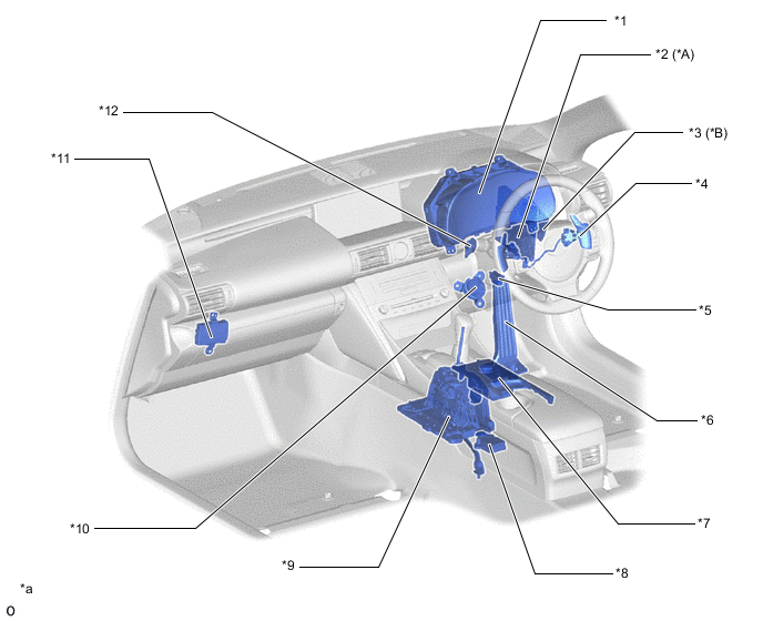
| *A | Models with Stop and Start System | *B | Models with Dynamic Radar Cruise ControlSystem |
| *1 | Combination Meter Assembly
|
*2 | Engine Stop and Start ECU |
| *3 | Driving Support ECU Assembly | *4 | Shift Paddle Switch (Transmission Shift Switch Assembly) |
| *5 | DLC3 | *6 | Accelerator Pedal Sensor Assembly |
| *7 | Combination Switch Assembly
|
*8 | Yawrate Sensor |
| *9 | Transmission Floor Shift Assembly
|
*10 | Kick Down Switch Assembly |
| *11 | Network Gateway ECU | *12 | Stop Light Switch Assembly |
| *a | The illustrations shown are examples only. | - | - |
Figure 8. LHD Models
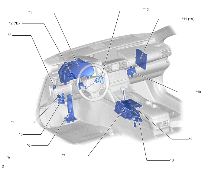
| *A | Models with Stop and Start System | *B | Models with Dynamic Radar Cruise Control System |
| *1 | Combination Meter Assembly
|
*2 | Driving Support ECU Assembly |
| *3 | Stop Light Switch Assembly | *4 | DLC3 |
| *5 | Kick Down Switch Assembly | *6 | Accelerator Pedal Sensor Assembly |
| *7 | Transmission Floor Shift Assembly
|
*8 | Yawrate Sensor |
| *9 | Combination Switch Assembly
|
*10 | Network Gateway ECU |
| *11 | Engine Stop and Start ECU | *12 | Shift Paddle Switch (Transmission Shift Switch Assembly) |
| *a | The illustrations shown are examples only. | - | - |