ROAD SIGN ASSIST SYSTEM
-
FUNCTION OF MAIN COMPONENTS
-
The main components in the RSA have the following functions.
Item Function Forward Recognition Camera Monocular Camera Sensor Captures road signs. Forward Recognition Camera ECU Performs RSA system control based on information of road signs captured by the monocular camera sensor. Millimeter Wave Radar Sensor Assembly detects object information and sends signal to forward recognition camera. Steering Sensor Detects the steering direction and angle of the steering wheel. Yawrate Sensor Detects the yaw rate and lateral/longitudinal deceleration of the vehicle and transmits the signal to the forward recognition camera. Combination Meter Assembly Multi-information Display
-
Displays road signs recognized by the forward recognition camera.
-
The RSA system can be turned on and off through the settings tab.
Buzzer Sounds for speed limit exceeded and no overtaking notifications.*1 Steering Pad Switch Assembly Meter Control Switches Sends a multi-information operating signal to the forward recognition camera. ECM Sends a shift position signal to the forward recognition camera. Brake Actuator Assembly Skid Control ECU Sends a vehicle speed signal from the speed sensor to the forward recognition camera. Main Body ECU (Multiplex Network Body ECU) Sends country specification information signals to the forward recognition camera. Air Conditioning Amplifier Assembly Sends the outside temperature signal to the forward recognition camera. Radio Receiver Assembly*2
-
Sends map information to the forward recognition camera.
-
Performs coordinated control with the forward recognition camera in regards to speed limit information.
Central Gateway ECU (Network Gateway ECU) Relays and transmits each CAN communication data signal. *1: The threshold can be adjusted to 1 of 3 levels through the customization function
*2: Models with navigation system
-
-
-
FUNCTION
-
The RSA system recognizes the following traffic signals using the forward recognition camera.
Category Sign Type Example of Recognizable Sign Speed Limit Round maximum speed limit/End of speed limit 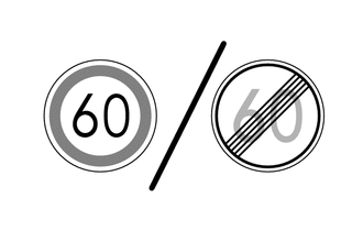
No Overtaking No overtaking/End of no overtaking 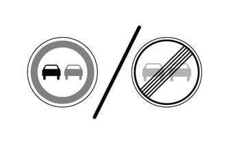
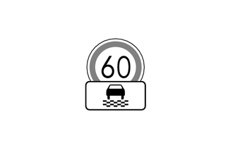
Supplemental Signs Road condition signs Ramp Way 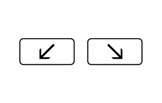
Rain 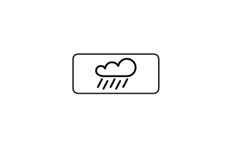
Wet 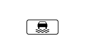
Ice 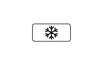
End of Prohibition 
No entry* 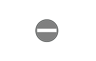
*: Models with navigation system
-
The RSA system recognizes the following traffic signals using the forward recognition camera.
Category Display Example Details Speed Limit Related 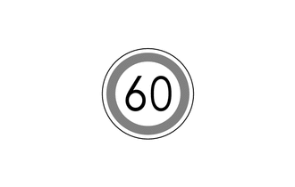
-
Informs the driver of the maximum speed limit of the currently driven road.
-
The displayed sign reflects the speed limit on the recognized sign.
No Overtaking Related 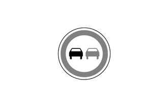
Informs the driver when they are in a no overtaking zone on the currently driven road. No Entry Related* 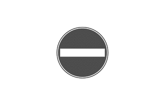
Informs the driver that there are vehicle entry restricted sections on the currently driven road. All Canceled (All restrictions canceled. Return to default road regulations.) Informs the driver when all applicable prohibitions, such as speed limit and no overtaking, have ended. Speed Limit with Supplemental Sign Related Ramp Way 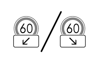
Informs the driver of the ramp way direction. However, this item is not displayed when making a lane change without operating the turn signal light. Rain 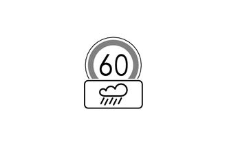
Informs the driver of the maximum speed limit on the currently driven road when it is raining or the road surface is wet. Speed Limit with Supplemental Sign Related Ice 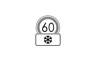
Informs the driver of the maximum speed limit on the currently driven road when there is accumulated snow or ice. Blank 
The display is blank when the system is unable to recognize a supplemental sign. *: Models with navigation system
-
-
Notification functions are used in the RSA system which invert the colors of displayed signs, flash signs, etc. to notify the driver.
-
Speed Limit Exceeded Notification
-
While a speed limit sign is displayed, if the actual vehicle speed exceeds the speed limit plus a designated threshold*, the colors of the displayed sign are inverted. For example, if the threshold is set to 5 km/h and the speed limit sign is 60 km/h, the colors of the displayed sign are inverted when the actual vehicle speed exceeds 65 km/h. Furthermore, the system also inverts a speed limit sign with supplemental sign in the same way. However, the system does not invert the colors of the supplemental sign.
-
The buzzer may be set to sound during notifications through the customization function. However, if a speed limit recognized from a speed limit with supplemental sign is exceeded, the buzzer does not sound.
-
This notification is judged according to the speed units estimated by the monocular camera sensor. When moving to a region with different speed units, notifications may be incorrectly issued until learning is complete. (The user can change speed units of the meter for the given region, therefore displays and notifications can be correctly issued directly after moving to a region with different speed units).
Tech Tips
*: The threshold can be adjusted to 1 of 3 levels through the customization function.
Notification Method Display Example Inverted Display 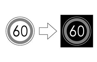
-
-
No Overtaking Notification
-
While a no overtaking sign is displayed, if the system detects that the vehicle is attempting to overtake another vehicle, the system flashes the displayed sign.
-
The buzzer may be set to sound during notifications through the customization function.
Notification Method Display Example Flashing Display 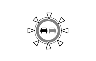
-
-
No-entry Notification*
-
While a no entry sign is displayed, if the system detects that the driver is driving on a road where entry is prohibited, based on map information, the system flashes the displayed sign.
-
The buzzer may be set to sound during notifications through the customization function.
Notification Method Display Example Flashing Display 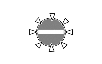
*: Models with navigation system
-
-
-
The RSA can be turned on or off through the settings tab of the multi-information display.
-
A customization function is used for the RSA, which allows settings such as the notification method and level for exceeding the speed limit to be changed. Setting changes are made through the customization tab of the multi-information display. Refer to the Repair Manual for details.
-
-
SYSTEM CONTROL
-
RSA Control Pattern 1
-
After a road sign is recognized by the forward recognition camera and the vehicle passes by, the sign is displayed on the multi-information display.
-
While a sign is displayed on the multi-information display, if a new road sign is not recognized within a specified distance, display of the current sign is turned off.
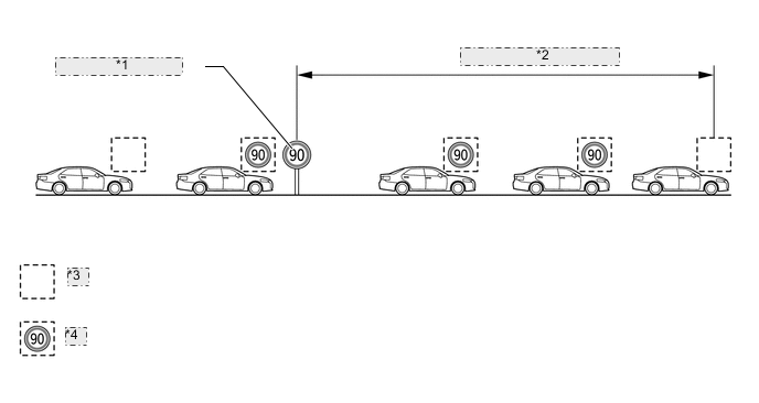
*1 Road Sign Recognized *2 Specified Distance Driven *3 Sign Display Off *4 Sign Display On
-
-
RSA Control Pattern 2
-
When the engine switch is turned off while a sign is displayed on the multi-information display, the same sign is displayed when the engine switch is turned ON again.
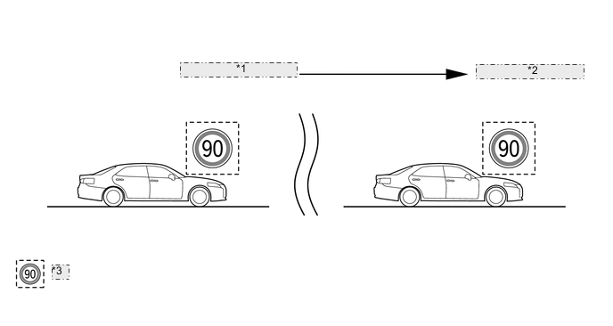
*1 Engine Switch off (IG) *2 Engine Switch on (IG) *3 Sign Display On
-
-
RSA Control Pattern 3
-
While a sign is displayed on the multi-information display, the sign is turned off when turning left or right onto a new road.
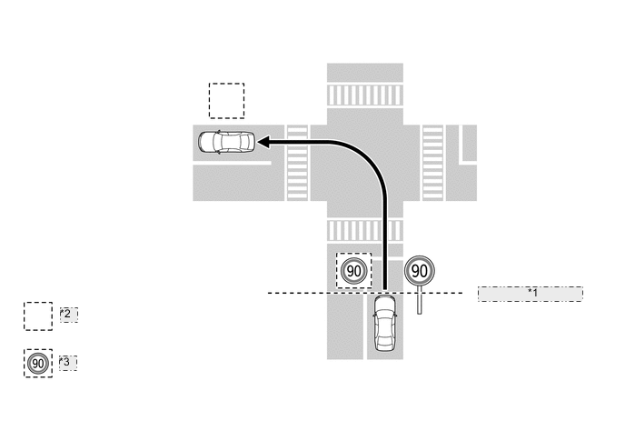
*1 Road Sign Recognized *2 Sign Display Off *3 Sign Display On
-
-
-
DIAGNOSIS
-
If a malfunction is detected in the RSA system the forward recognition camera. cancels the RSA, sounds the buzzer in the combination meter assembly, and displays a message on the multi-information display to inform the driver of the malfunction.
-
At the same time, the malfunction is stored in memory as a Diagnostic Trouble Code (DTC). When a Global TechStream (GTS) is connected to the DLC3, the DTC can be read. For details, refer to the Repair Manual.
-