AUTOMATIC TRANSMISSION SYSTEM
-
FUNCTION OF MAIN COMPONENTS
Component Function ATF Warmer (Transmission Oil Cooler)
-
Warms up the ATF quickly.
-
Keeps the ATF temperature higher (within limits).
Torque Converter Assembly
-
Transmits the engine power to the transmission.
-
Increases engine torque.
Oil Pump Assembly Provides oil pressure necessary for the transmission operation. No. 1 Clutch (C1) Connects the input shaft, F4 and the intermediate shaft. No. 2 Clutch (C2) Connects the input shaft and the center planetary carrier. No. 3 Clutch (C3) Connects the input shaft and the front planetary sun gear. No. 4 Clutch (C4) Connects the input shaft and the intermediate shaft. No. 1 Brake (B1) Prevents the front planetary carrier from turning either clockwise or counterclockwise. No. 2 Brake (B2) Prevents the front and center planetary ring gears from turning either clockwise or counterclockwise. No. 3 Brake (B3) Prevents the outer race of F2 from turning both clockwise and counterclockwise. No. 4 Brake (B4) Prevents the center planetary carrier and the rear planetary ring gear from turning either clockwise or counterclockwise. No. 1 1-way Clutch (F1) Prevents the front planetary carrier from turning counterclockwise. No. 2 1-way Clutch (F2) Prevents the front planetary sun gear from turning counterclockwise when B3 is operating. No. 3 1-way Clutch (F3) Prevents the center planetary carrier and the rear planetary ring gear from turning counterclockwise. No. 4 1-way Clutch (F4) Prevents the intermediate shaft from turning counterclockwise. Planetary Gears Change the power transmission route in accordance with clutch and brake operation, and increase or decrease output shaft revolution accordingly. Shift Solenoid Valve S1 Switches the 1-2 shift valve and the SL1 relay valve. Shift Solenoid Valve S2 Switches the 2-3 shift valve and the 5-6 shift valve. Shift Solenoid Valve S3 Switches the 3-4 shift valve. Shift Solenoid Valve S4 Switches the 4-5 shift valve, the SL1 relay valve and the reverse sequence valve. Shift Solenoid Valve SR Switches the clutch apply relay valve and the B1 apply relay valve. Shift Solenoid Valve SL1
-
Controls clutch pressure.
-
Controls accumulator back pressure.
Shift Solenoid Valve SL2 Controls brake pressure. Shift Solenoid Valve SLT (Line Pressure Control Solenoid Assembly)
-
Controls line pressure.
-
Controls accumulator back pressure.
Shift Solenoid Valve SLU (Lock Up Control Solenoid Assembly) Controls lock-up clutch pressure. ATF Temperature Sensor Detects the ATF temperature. Transmission Revolution Sensor (NT) Detects the input speed of the transmission. Transmission Revolution Sensor (SP2) Detects the output speed of the transmission. Park/Neutral Position Switch Assembly Detects the shift lever position (P, R, N, D). Transmission Control Switch
-
Detects that the shift lever is in M.
-
Detects the driver's upshift and downshift operations when the shift lever is in M.
Shift Paddle Switch (Transmission Shift Switch Assembly) Detects the driver's upshift and downshift operations when the shift lever is in D or M. Combination Switch Assembly Drive Mode Select Selects the drive mode (ECO, NORMAL, SPORT*1, SPORT S*2 or SPORT S+*2). SNOW Switch*3 Selects the SNOW mode. Combination Meter Assembly MIL Illuminates or blinks to inform the driver when the ECM detects a malfunction. Multi-information Display
-
Displays the shift lever position.
-
Displays the shift range.
-
Displays the gear position.
-
Displays the drive mode.
-
Displays the message when the ATF is at a high temperature.
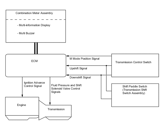
Multi Buzzer Sounds when downshift operation is rejected in M mode. ECM
-
Controls each shift solenoid valve and engine output in response to a signal from each sensor and switch.
-
When the ECM detects a malfunction, it makes a diagnosis and memorizes the failed section.
Skid Control ECU Sends the information about the operation conditions of the brake control system to the ECM. Driving Support ECU Assembly*4 Sends the information about the operation conditions of the dynamic radar cruise control system to the ECM. Tech Tips
*1: Except F SPORT
*2: For F SPORT
*3: Except models for G.C.C. Countries
*4: Models with dynamic radar cruise control system
-
-
SYSTEM CONTROL
Electronic Control of Automatic Transmission Control Function Shift Timing Control The ECM sends current to shift solenoid valves S1, S2, S3, S4 and/or SR based on signals from various sensors in order to shift the gears. Line Pressure Control Actuates the shift solenoid valve SLT (line pressure control solenoid assembly) to control the line pressure in accordance with information from the ECM and the operating conditions of the transmission. Clutch Pressure Optimal Control The shift solenoid valve SL1 and shift solenoid valve SLT (line pressure control solenoid assembly) minutely control the clutch pressure in accordance with the engine output and driving conditions of the transmission. Clutch to Clutch Pressure Control Controls the pressure that is applied directly to B2 brake and C3 clutch by actuating the shift solenoid valves SL1 and SL2 in accordance with the ECM signals. Orifice Switching Control Prevents the oil pump from drawing air during extremely low temperatures while in 1st gear. Powertrain Cooperative Control Controls both the shift control and engine output control in an integrated way, thus achieving excellent shift characteristics and driveability. Coast Downshift Control To prevent engine speed from decreasing and thereby maintain fuel cut, the ECM performs downshifts before fuel cut ends. Multi-mode Transmission
-
The ECM appropriately controls the automatic transmission in accordance with the gear range selected using the shift lever or shift paddle switch (transmission shift switch assembly) while the shift lever is in M.
-
An improvement in manual operation response and driveability has been achieved by the gear hold control, lock-up control, super high response upshift control and blipping downshift control.
-
When the shift lever is in D, the driver can select a desired shift range using the shift paddle switch (transmission shift switch assembly).
Lock-up Timing Control The ECM sends current to the shift solenoid valve SLU (lock up control solenoid assembly) based on signals from various sensors and engages or disengages the lock-up clutch. Flex Lock-up Clutch Control Controls the shift solenoid valve SLU (lock up control solenoid assembly), provides an intermediate mode for when the lock-up clutch is between on and off, and increases the operating range of the lock-up clutch to improve fuel economy. Neutral Control* When the vehicle is stopped, the TCM disengages the transmission from the engineto improve fuel economy. Artificial Intelligence Shift Control (AI-shift Control) Based on the signals from various sensors, the ECM determines the road conditions and the intention of the driver. Thus, an appropriate shift pattern is automatically determined, thus improving driveability. 2nd Gear Start-off and Stop Control When the engine idling speed is high while the engine is warming up and the road surface is slippery, 2nd gear start-off and stop control for low-friction roads is automatically used in order to enhance control of driving force using the accelerator. Differential Protection Control When there is a large rotation difference between the left and right wheels, shifting will be prevented to protect the differential. ATF High Temperature Control When the ATF is at a high temperature, normal shifting characteristics will be changed to shifting characteristics which actively utilize the low gear range to prevent the oil temperature from rising further. Tech Tips
*: Models for China
-
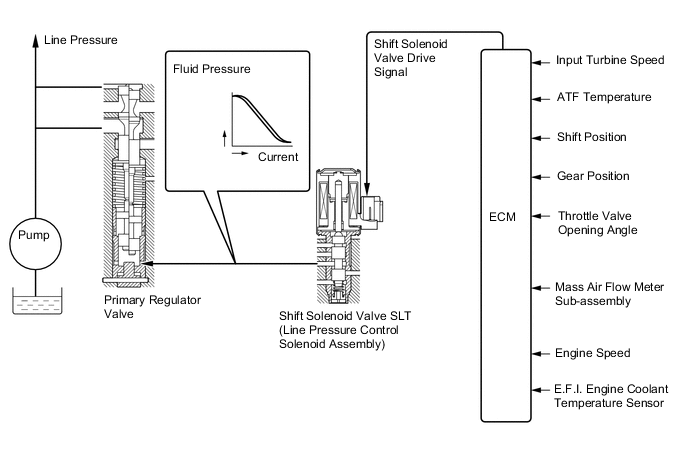
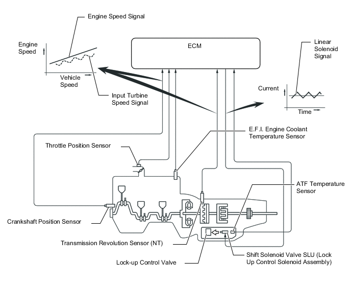
Line Pressure Control
-
In order to obtain predetermined line pressure characteristics in accordance with each sensor signal, the ECM activates the shift solenoid valve SLT (line pressure control solenoid assembly) to regulate the throttle pressure.
-
This makes it possible for the primary regulator valve to precisely and minutely control the line pressure in accordance with the engine output, thus providing smoother shift characteristics.
-
-
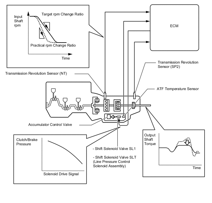
Clutch Pressure Optimal Control
-
The ECM monitors the signals from various types of sensors, such as the transmission revolution sensor (NT), allowing shift solenoid valve SL1 and shift solenoid valve SLT (line pressure control solenoid assembly) to minutely control the clutch pressure in accordance with engine output and driving conditions. As a result, smooth shift characteristics are achieved.
-
-
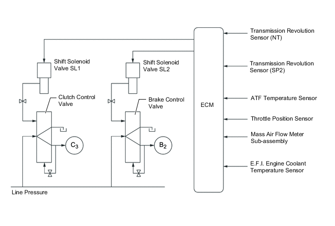
Clutch to Clutch Pressure Control
-
This control is used for shifting from 5th to 6th gear and from 6th to 5th gear.
-
The ECM actuates shift solenoid valves SL1 and SL2 in accordance with various signals. The output from these shift solenoid valves acts directly on control valves B2 and C3 in order to regulate the line pressure that acts on the B2 brake and C3 clutch.
-
High response and excellent shift characteristics have been achieved.
-
-
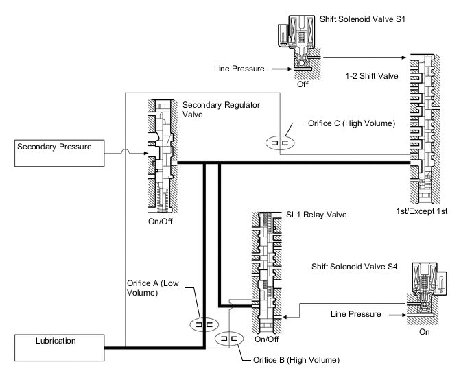
Orifice Switching Control
-
At extremely low temperatures, the ATF viscosity increases (becomes thick), making the oil pump susceptible to cavitation. For this reason, the orifice switching control reduces the volume of ATF in the hydraulic circuit and increases the volume of ATF drawn by the oil pump, in order to prevent the oil pump from cavitating.
-
While stopped in the 1st gear, the ECM turns off the shift solenoid valve S1 and turns on (normally off) the shift solenoid valve S4 in order to apply the line pressure to the 1-2 shift valve and the SL1 relay valve. The 1-2 shift valve and the SL1 relay valve close the ATF passage for the secondary pressure from the secondary regulator valve, thus causing the secondary pressure to pass through orifice A. As a result, the volume of ATF in the hydraulic circuit is reduced.
-
While stopped in a gear other than 1st, the secondary pressure from the secondary regulator valve travels through either or both of the 1-2 shift valve and SL1 relay valve, and passes through orifice B and C. As a result, the volume of the ATF in the hydraulic circuit is not reduced.
-
-
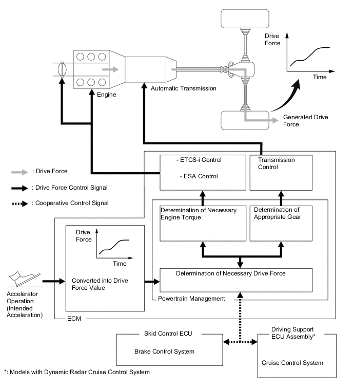
Powertrain Cooperative Control
-
Driving Response and Acceleration Management System (DRAMS) is used for this vehicle. This system integrally controls the engine, transmission and other driving related controls. By integrally controlling the engine and automatic transmission using this system, quick response and a high quality driving feel in accordance with the driver's intentions are achieved, such as when accelerating or decelerating or during gear shifts.
-
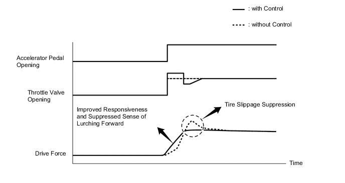
Throttle Control at Launch
-
The engine output is optimally controlled with Electronic Throttle Control System-intelligent (ETCS-i) in real-time in accordance with the transient force from the torque converter when the vehicle is launched. This achieves a "suppressed sense of lurching forward", "tire slippage suppression" and "improved responsiveness", ensuring excellent launch performance.
-
-
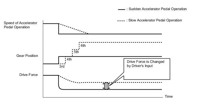
Deceleration Force Control
-
The ECM determines the gear position when the accelerator pedal is off (released completely) in accordance with the way the accelerator pedal is released (suddenly or slowly) during deceleration. In this way, unnecessary upshifts and downshifts are prevented when the accelerator pedal is off and subsequent smooth acceleration is ensured, matching the driver's intentions.
-
-
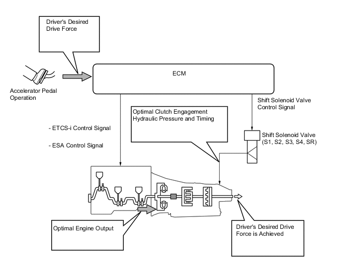
Transient Shifting Control
-
Through integrated control with Electronic Throttle Control System-intelligent (ETCS-i), Electronic Spark Advance (ESA), and electronic control of the engagement and release speed of clutch and brake hydraulic pressures, excellent response and shift shock reduction have been achieved.
-
-
Engine Torque Control
-
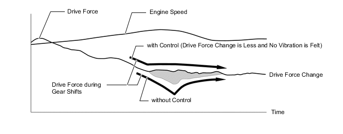
Engine torque control used during gear shifts has been added to the cooperative control of the engine torque control and clutch hydraulic pressure control performed during gear shifts. This enhances gear engagement characteristics during gear shifts and achieves smooth gear changes.
-
-
-
Coast Downshift Control
-
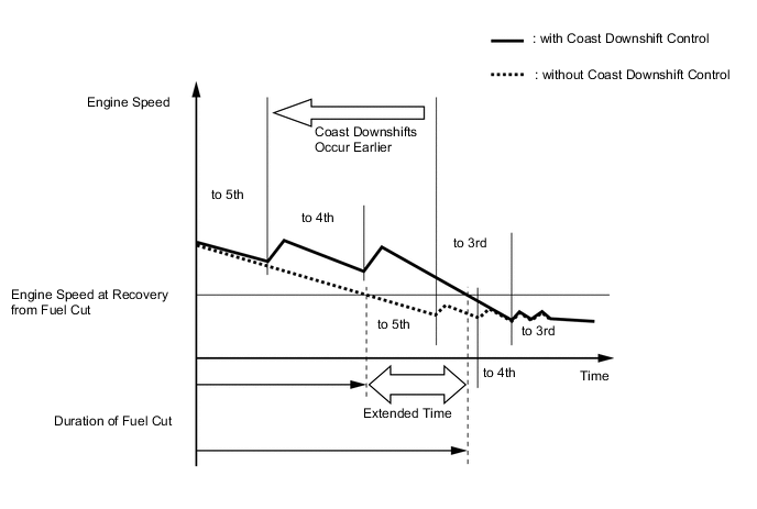
The ECM performs downshift control to prevent the engine speed from decreasing, thus keeping fuel cut control operating for as long as possible. In this way, the fuel economy is improved.
-
For this control, when the vehicle is in 6th gear and starts decelerating, the transmission downshifts from 6th to 5th and from 5th to 4th before fuel cut control ends so that fuel cut control continues operating.
-
-
Multi-mode Transmission
-
The driver can select the desired gear range by moving the shift lever to "+" (forward) or to "-" (backward) while the shift lever is in M. Also, the shift paddle switch (transmission shift switch assembly) can be used to change the gear range while the driver is holding the steering wheel. Thus, the driver is able to shift gears with a manual-like feel.
-
When the vehicle is being driven at a prescribed speed or higher, any attempt to shift to a lower range by operating the shift lever will not be executed, in order to protect the automatic transmission. In this case, the ECM sounds the multi buzzer in the combination meter assembly twice to alert the driver.
-
When the shift lever is in D, the driver can momentarily select a desired shift range by operating the shift paddle switch (transmission shift switch assembly). Automatic shifting will be reinstated under the following conditions:
- The vehicle has stopped.
- The driver continues to push the shift paddle switch (transmission shift switch assembly) in the "+" direction longer than 1 second.
- The driver depresses the accelerator pedal longer than a predetermined length of time.
-
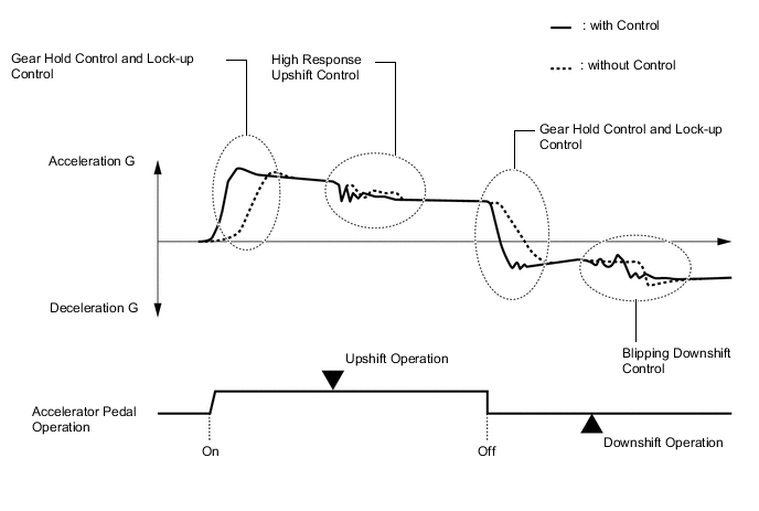
When the shift lever is in M, the gear hold control, lock-up control, high response upshift control and blipping downshift control are used in order to improve response in accordance with the driver's operation of the accelerator pedal, shift lever or shift paddle switch (transmission shift switch assembly), and to improve gear shift feeling.
-
Gear Hold Control
-
Gear shifting will not be performed under gear hold control as long as the shift lever or shift paddle switch (transmission shift switch assembly) is not operated. This makes it possible to make efficient use of highest engine speeds. However, in the following cases, operation of gear hold control is limited.
Automatic shifting when the shift lever is in M
-
When the ATF or engine coolant temperature is low, gear shifting will be performed automatically.
-
When the ATF temperature is high, gear shifting will be performed automatically.
-
-
Lock-up Control
-
While the shift lever is in M, lock-up control operates from 4th gear, transmitting the changes in engine power directly to the output shaft, the same way as with a manual transmission, and thus, direct response to the accelerator operation is achieved.
-
-
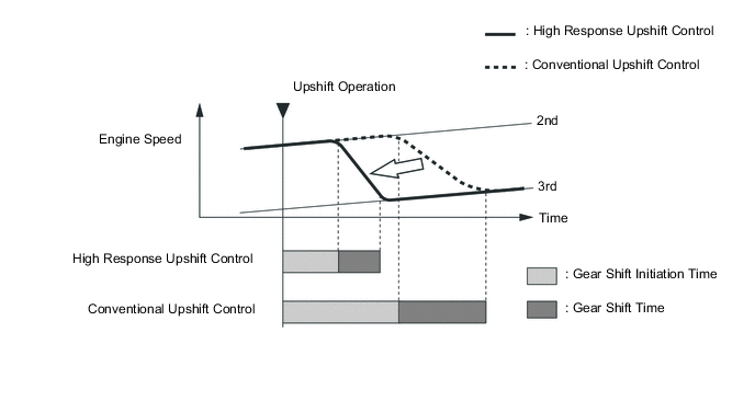
High Response Upshift Control
-
The high response upshift control achieves highly responsive upshift operation using the clutch to clutch pressure control, which regulates each clutch and brake quickly and precisely, and by the powertrain cooperative control, which optimally regulates engine torque during shifting.
-
-
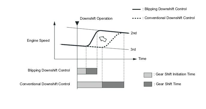
Blipping Downshift Control
-
The blipping downshift control regulates each clutch and brake using the clutch to clutch pressure control, allowing them to be engaged smoothly and disengaged quickly. In addition, fuel injection volume is increased and engine speed is boosted by the powertrain cooperative control, thus ensuring engine brake force. In this way, a smooth and quick downshift is achieved.
-
-
-
Lock-up Timing Control
-
The ECM operates the lock-up timing control in order to improve the fuel economy.
Lock-up Timing Control Operation Gear Shift Lever Position Shift Range (Fixed Range Mode*) D,D6 D5 D4 1st X X X 2nd X X X 3rd X X X 4th X X ○ 5th ○ ○ - 6th ○ - - Tech Tips
*: When the shift paddle switch (transmission shift switch assembly) is operated while the shift lever is in D.
○: Operates
X: Does not operate
-: Not applicable
-
-
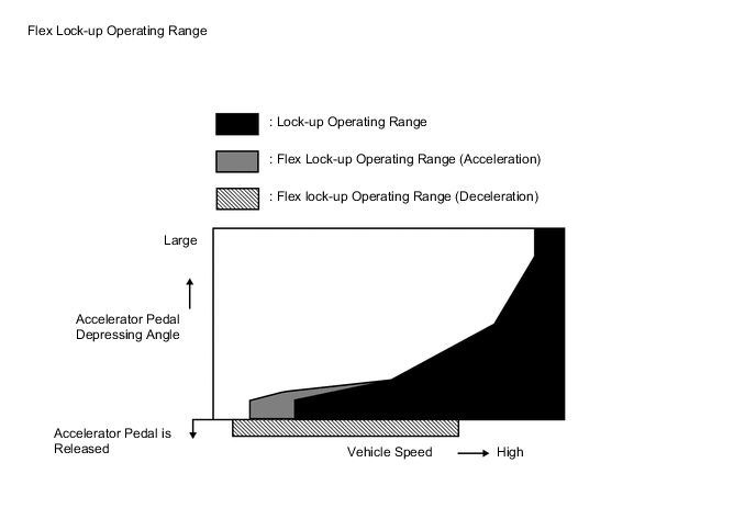
Flex Lock-up Clutch Control
-
In the low-to-mid-speed range, this flex lock-up clutch control regulates the shift solenoid valve SLU (lock up control solenoid assembly) to provide an intermediate mode between the on and off operations of the lock-up clutch in order to improve the energy transmitting efficiency. As a result, the operating range of the lock-up clutch has been increased and fuel economy has been improved.
Flex Lock-up Clutch Control Operation Gear Shift Lever Position Shift Range (Fixed Range Mode*1) D,D6 D5 D4 1st X X X 2nd X X X 3rd ○ ○ ○ 4th ○*2 ○*2 ○*2 5th ○*2 ○*2 - 6th ○*2 - - Tech Tips
*1: When the shift paddle switch (transmission shift switch assembly) is operated while the shift lever is in D.
*2: Flex lock-up clutch control operates during deceleration.
○: Operates
X: Does not operate
-: Not applicable
-
-
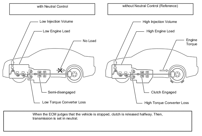
Neutral Control
-
Neutral control is used to disengage the transmission from the engine while the vehicle is stopped.
-
When the shift lever is in D and the vehicle is stopped, the ECM semi-disengages the forword clutch and the brake. This reduces the load on the engine and improves fuel economy while the vehicle is stopped.
-
-
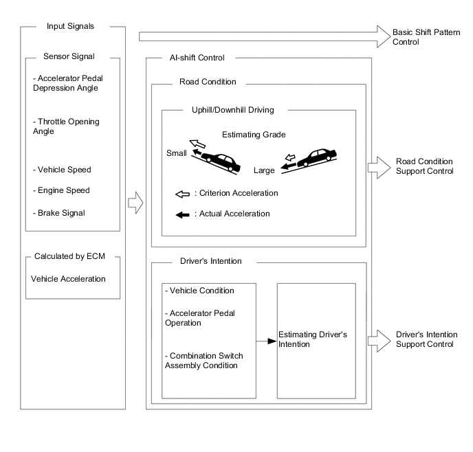
Artificial Intelligence Shift Control (AI-shift Control)
-
The AI-shift control determines optimal transmission control based on input signals and automatically changes the shift pattern. As a result, a high caliber of transmission operation is achieved.
-
The AI-shift control includes a road condition support control and a driver's intention support.
-
The AI-shift control is effected with the shift lever in D, based on the accelerator pedal and brake operation data. The AI-shift control will be canceled when the shift lever is moved to a position other than D.
-
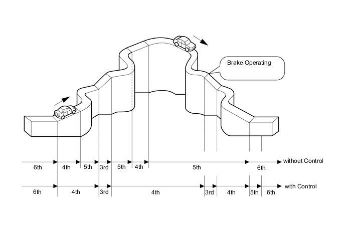
Road Condition Support Control
-
The ECM identifies the throttle valve opening angle, accelerator pedal opening angle and vehicle speed to determine whether the vehicle is being driven uphill or downhill. Unnecessary upshift is restrained to automatically achieve optimal drive force at all times while driving uphill. Downshift is automatically conducted to achieve optimal engine brake force, while driving downhill.
-
-
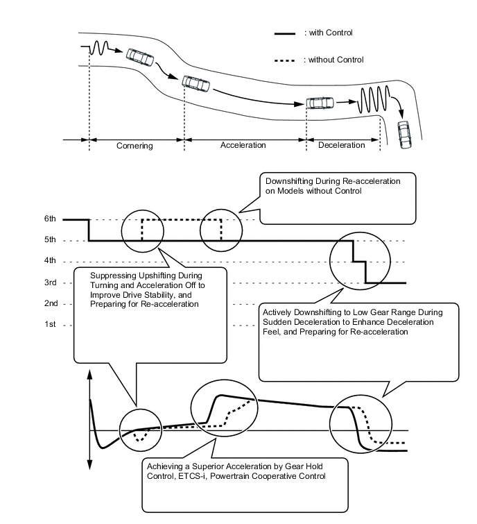
Driver's Intention Support Control
-
The driver's intention support control is estimated based on the accelerator pedal operation, vehicle condition and a shift pattern that is well-suited to the driver's intention is selected without operating the switch.
-
When the drive mode (SPORT*1, SPORT S*2 or SPORT S+*2) is selected, the driver's intention is assumed even when in the automatic shifting mode, thus enabling a dynamic drive.
-
By actively utilizing the low gear range to suppress unnecessary shifting, an improvement in the vehicle stability and acceleration performance has been achieved.
Tech Tips
*1: Except F SPORT
*2: For F SPORT
-
-
-
-
FUNCTION
-
Drive Mode Select Function
-
The drive mode can be selected by operating the drive mode select or SNOW switch.
-
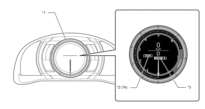
The selected drive mode will be shown on the multi-information display in the combination meter assembly.
-
The drive characteristics of each drive mode are as follows:
Drive Mode Outline ECO Transmission characteristics which prioritize fuel efficient driving are used to ensure low fuel consumption compared with that of NORMAL mode.This drive mode provides optimum driveability. NORMAL This drive mode provides optimum driveability. SPORT Mode*1
SPORT S Mode*2
The ECM improves acceleration performance and responsiveness by controlling the opening of the throttle and by changing the shift point of the transmission, thus achieving a sporty drive. SPORT S+ Mode*2 In addition to the control when in SPORT S mode, the suspension control system, brake control system and steering control system have been integrated to shift to SPORT S+ mode, improved operability and stability have been aimed for even without losing comfort and a control which enables operation appropriate to the driver's intention is performed. SNOW*3 The ECM improves starting-off performance and acceleration performance on slippery road surfaces such as snow on which the wheels may spin by controlling to restrain drive force more than when in NORMAL mode. Tech Tips
*1: Except F SPORT
*2: For F SPORT
*3: Except Models for G.C.C. Countries
Figure 1. Combination Switch Assembly (The illustration is a representative example.)
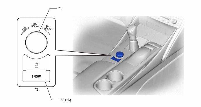
*A Except Models for G.C.C. Countries - - *1 Drive Mode Select *2 SNOW Switch *3 Combination Switch Assembly - - Figure 2. Optitron Meter (The illustration is a representative example.)
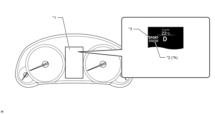
*A Except Models for G.C.C. Countries - - *1 Multi-information Display *2 SNOW Mode Indicator Light *3 Drive Mode Indicator Light - - Figure 3. TFT LCD Meter
*A Except Models for G.C.C. Countries - - *1 Multi-information Display *2 SNOW Mode Indicator Light *3 Drive Mode Indicator Light - - -
-
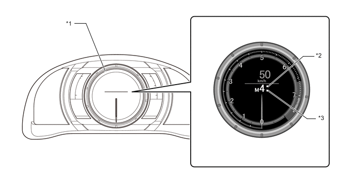
Gear Shift Indicator System
-
Gear shift indicator system is a system to promote upshifting to the fuel-efficient and optimalgear ranges in accordance with the driving conditions such as the accelerator pedal opening andthe vehicle speed, etc. when the vehicle is running while the shift lever is in M.
-
By driving in accordance with the upshifting recommendations indicated by the gear shift indicator in the multi-information display, the driver can enhance environmental performance, improve fuel economy and reduce exhaust gas output within the limits of engine performance.
Figure 4. Optitron Meter
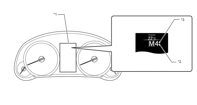
*1 Multi-information Display *2 Gear Shift Indicator Light "-" (backward) *3 Gear Shift Indicator Light "+" (forward) - - Figure 5. TFT LCD Meter
*1 Multi-information Display *2 Gear Shift Indicator Light "-" (backward) *3 Gear Shift Indicator Light "+" (forward) - - -
-
-
FAIL-SAFE
-
The fail-safe function minimizes the loss of operability when an abnormality occurs in a sensor or a shift solenoid valve.
Fail-safe Control List Malfunction Part Function Transmission Revolution Sensor (NT)
-
During a transmission revolution sensor (NT) malfunction, shift control is effected based on the transmission revolution sensor (SP2) signal.
-
During a transmission revolution sensor (NT) malfunction, upshifting to 5th and 6th, AI-shift control and flex lock-up clutch control are prohibited.
Transmission Revolution Sensor (SP2)
-
During a transmission revolution sensor (SP2) malfunction, shift control is effected based on the transmission revolution sensor (NT) signal.
-
During a transmission revolution sensor (SP2) malfunction, upshifting to 5th and 6th, AI-shift control and flex lock-up clutch control are prohibited.
ATF Temperature Sensor During an ATF temperature sensor malfunction, upshifting to 5th and 6th, and flex lock-up clutch control are prohibited. Shift Solenoid Valves S1, S2, S3, S4 and SR
-
When one of the shift solenoid valves listed left malfunctions, current to the failed shift solenoid valve is cut off.
-
Shift control is changed to a fail-safe mode to shift gears using the normal shift solenoid valves to allow continued driving.
Shift Solenoid Valves SL1 and SL2 During a shift solenoid valve SL1 or SL2 malfunction, upshifting to 5th and 6th, and flex lock-up clutch control are prohibited. Shift Solenoid Valve SLT (Line Pressure Control Solenoid Assembly) During a shift solenoid valve SLT (line pressure control solenoid assembly) malfunction, the current to the shift solenoid valve is stopped. Because this stops line pressure optimal control, the shift shock will increase. However, shifting is effected based on normal clutch pressure control. Shift Solenoid Valve SLU (Lock Up Control Solenoid Assembly) During a shift solenoid valve SLU (lock up control solenoid assembly) malfunction, the current to the shift solenoid valve is stopped. Because this stops lock-up timing control and flex lock-up clutch control, fuel economy decreases. -
-
DIAGNOSIS
-
When the ECM detects a malfunction, it makes a diagnosis and memorizes the failed section. Furthermore, the ECM illuminates or blinks the MIL in the combination meter assembly to inform the driver.
-
The ECM will also store the Diagnostic Trouble Codes (DTCs) of the malfunctions.
-
The DTCs can be read by connecting the Global TechStream (GTS) to the DLC3.
-
For details, refer to the Repair Manual.
-