AUTOMATIC TRANSMISSION SYSTEM
-
CONSTRUCTION
-
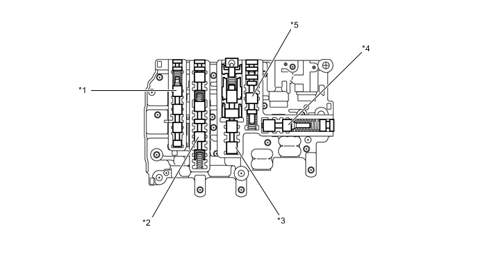
The transmission valve body assembly consists of the upper (No. 1 and No. 2) and lower (No. 1 and No. 2) valve bodies and 9 shift solenoid valves.
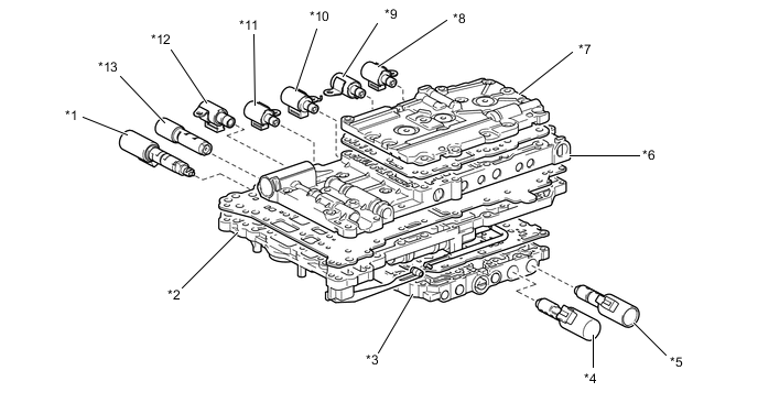
*1 Shift Solenoid Valve SLT (Line Pressure Control Solenoid Assembly) *2 No. 1 Lower Valve Body *3 No. 2 Lower Valve Body *4 Shift Solenoid Valve SL2 *5 Shift Solenoid Valve SLU (Lock up Control Solenoid Assembly) *6 No. 1 Upper Valve Body *7 No. 2 Upper Valve Body *8 Shift Solenoid Valve S3 *9 Shift Solenoid Valve S2 *10 Shift Solenoid Valve S4 *11 Shift Solenoid Valve S1 *12 Shift Solenoid Valve SR *13 Shift Solenoid Valve SL1 - - Figure 1. No. 1 Upper Valve Body
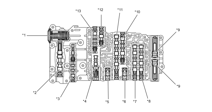
*1 C1 Accumulator *2 Secondary Regulator Valve *3 Lock-up Relay Valve *4 Lock-up Control Valve *5 C3 Check Valve *6 B4 Outer Check Valve *7 2-3 Valve *8 3-4 Valve *9 B2 Accumulator *10 Sequence Valve *11 1-2 Shift Valve *12 Clutch Control Valve *13 Clutch Apply Relay Valve - - Figure 2. No. 2 Upper Valve Body
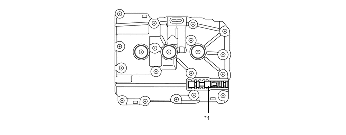
*1 C3 Apply Relay Valve - - Figure 3. No. 1 Lower Valve Body
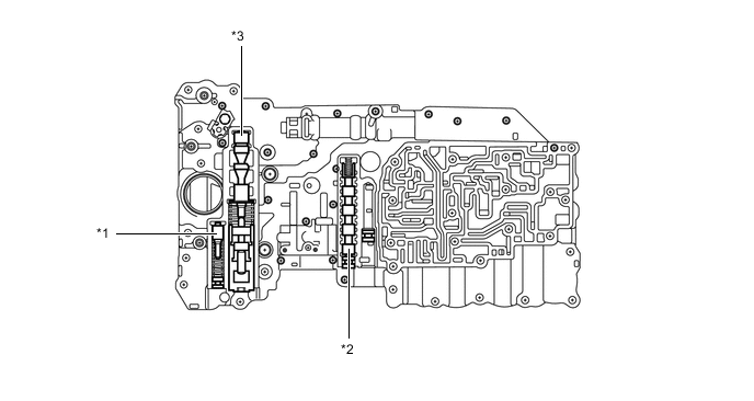
*1 SLT Damper *2 4-5 Shift Valve *3 Primary Regulator Valve - - Figure 4. No. 2 Lower Valve Body
*1 B1 Apply Relay Valve *2 Solenoid Relay Valve *3 Accumulator Control Valve *4 Solenoid Modulator Valve *5 Brake Control Valve - - -