FUEL SYSTEM
-
CONSTRUCTION
-
A fuel pump (for low pressure), fuel pump filter and 2 fuel main valve assemblies with integrated fuel suction tube with pump and gauge assembly are used.
-
A brushless motor is used for the fuel pump (for low pressure). Loss due to brush contact resistance is eliminated, reducing power consumption and achieving improved fuel economy.
-
The fuel pressure of the low-pressure fuel system is controlled by the fuel pump speed.
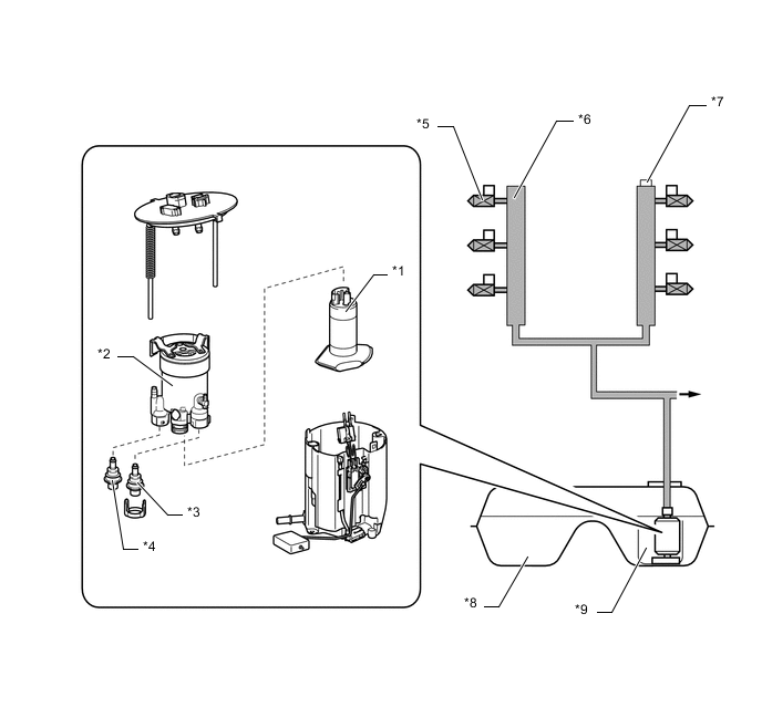
*1 Fuel Pump (for Low Pressure) *2 Case
-
Fuel Filter
*3 Fuel Main Valve Assembly (for Low Pressure) *4 Fuel Main Valve Assembly (for High Pressure) *5 Fuel Injector Assembly (for Port Injection) *6 Fuel Delivery Pipe with Sensor Assembly (for Port Injection) *7 Fuel Pressure Sensor (for Low Pressure) *8 Fuel Tank Assembly *9 Fuel Suction Tube with Pump and Gauge Assembly - - Tech Tips
Conceptual Diagram of Structure:
Figure 1. Brushless Motor
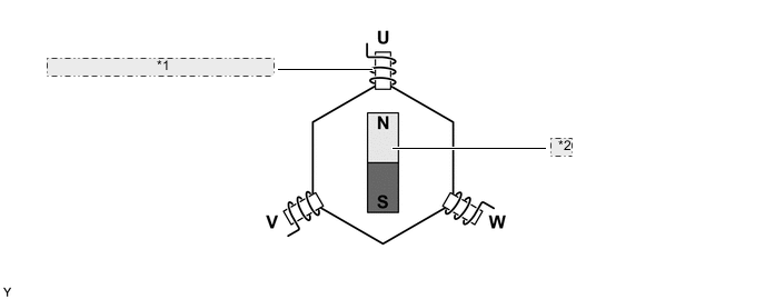
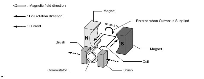
*1 Poles of Each Coil Switch in Order (Electronically Controlled) *2 Magnet Rotation Figure 2. Brush Motor
-
-