FUEL SYSTEM
-
OUTLINE
-
The 4GR-FSE engine uses a Direct injection 4-stroke gasoline engine (D-4) system that has the fuel injectors installed on the combustion chamber. These injectors inject the fuel pressurized by the high-pressure fuel pump directly into the combustion chamber.
-
This system effects comprehensive control of the fuel injection timing, air fuel ratio, throttle valve opening angle, etc., to achieve both high power output and low exhaust emissions.
-
A fuel returnless system is used to reduce evaporative emissions.
-
Fuel cut control is used to stop the fuel pump assembly (for low pressure) when an SRS airbag is deployed.
-
A single-slit, high-pressure slit nozzle fuel injector assembly is used.
-
An On-board Refueling Vapor Recovery (ORVR) system is used.* For details, see 4GR-FSE Emission Control. Click here
*: Destination package for South Korea
-
A cold start fuel injector assembly is provided in the surge tank to enhance cold starting performance.*
*: Models with cold start fuel injector assembly
-
-
MAIN FEATURES
-
D-4 System
-
The Direct injection 4-stroke gasoline engine (D-4) system has the injector assembly installed on the combustion chamber.
-
Fuel sent from the fuel tank assembly is delivered to fuel pump assembly (high pressure) by the fuel pump assembly (low pressure). The fuel is pressurized by the fuel pump assembly (for high pressure) and injected from the fuel injector assembly to the combustion chamber.
-
Mainly consisting of a fuel pump assembly (high pressure), fuel delivery pipe, and slit nozzle type injectors, this system effects optimal control for combustion by controlling the fuel pressure, injection volume, and the injection timing via the ECM and EDU (injector driver).
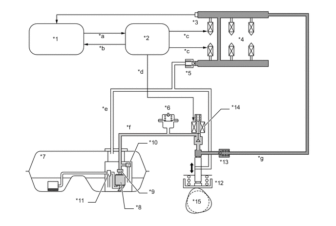
*1 ECM *2 EDU (Injector Driver) *3 Fuel Pressure Sensor *4 Fuel Injector Assembly *5 Fuel Relief Valve Assembly *6 Fuel Pressure Pulsation Damper Assembly *7 Fuel Tank Assembly *8 Fuel Pump Assembly (for Low Pressure) *9 Fuel Filter Assembly *10 Fuel Pressure Regulator Assembly *11 Jet Pump *12 Fuel Pump Assembly (for High Pressure) *13 Check Valve *14 Spill Control Valve *15 Exhaust Camshaft (Cam to Drive Fuel Pump) - - *a Spill Control Valve Drive Indication Signal *b Spill Control Valve Operation Confirmation Signal *c Injector Drive Signal *d Spill Control Valve Drive Signal *e High-pressure Fuel Return Pipe *f Low-pressure Fuel Pipe *g High-pressure Fuel Pipe - -
-
-