FUEL SYSTEM
-
CONSTRUCTION
-
Aluminum alloy fuel delivery pipes are used for the fuel delivery pipe sub-assembly (for direct injection).
-
A fuel pressure sensor and a fuel relief valve assembly are installed on the fuel delivery pipe.
-
An injector clamp is provided for each area of the fuel delivery pipe where a fuel injector assembly (for direct injection) is installed. This clamp applies a constant spring force to the injector to prevent the injector from moving when the combustion pressure is applied to the injector while the engine is being started, during which the fuel pressure is low. As a result, the clamp increases the sealing performance of the injector, while reducing vibration and noise.
-
O-rings and backup rings are used in the areas in which the fuel injector assembly (for direct injection) and fuel delivery pipe (for direct injection) are joined. This reduces the transmission of the operating sounds of the fuel injector assembly (for direct injection), enhances quiet operation, and ensures the sealing performance of the joined areas.
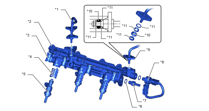
*1 No. 3 Fuel Pipe Assembly *2 Fuel Delivery Pipe RH (for Direct Injection) *3 Fuel Delivery Pipe LH (for Direct Injection) *4 Injector Clamp *5 Fuel Injector Assembly (for Direct Injection) *6 Gasket *7 Fuel Relief Valve Assembly *8 Fuel Pressure Sensor *9 No. 2 Fuel Pipe Assembly *10 O-ring *11 Backup Ring - - -
Fuel Relief Valve Assembly
-
A relief valve is provided in the fuel delivery pipe sub-assembly. When the fuel pressure in the fuel delivery pipe sub-assembly rises above (15.3 MPa), the fuel relief valve assembly limits the pressure by returning fuel to the fuel tank assembly.

*a from Fuel Delivery Pipe Sub-assembly (for Direct Injection) (Bank 2) *b Fuel Relief Valve Assembly Cross Section *c Fuel Outlet (to Fuel Tank Assembly) - -
-
-