BODY STRUCTURE
-
FUNCTION
-
Safety Features
-
Impact Absorbing Structure for Frontal Collision
-
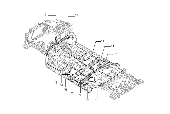
The front side members utilize ultra high tensile strength steel in a construction to absorb and disperse energy in a frontal collision.
-
The use of under members enables a construction that disperses load from the radiator supports.
-
Door beltline reinforcements are strengthened to optimize dispersal of collision energy to the front pillar, door beltline, and rocker panel.
-
The use of a crossmember in the dash panel enables a construction that disperses load from the front side members to the floor member and upper body.
-
The use of members on the front floor at the sides of the tunnel enables a construction that achieves tunnel strength and dispersal of load from the front side members.
-
Impact absorbing pads with sound absorbing performance are installed to the vehicle body from the lower surface of the dash panel to the front of the floor as a measure to reduce leg injuries in a collision.
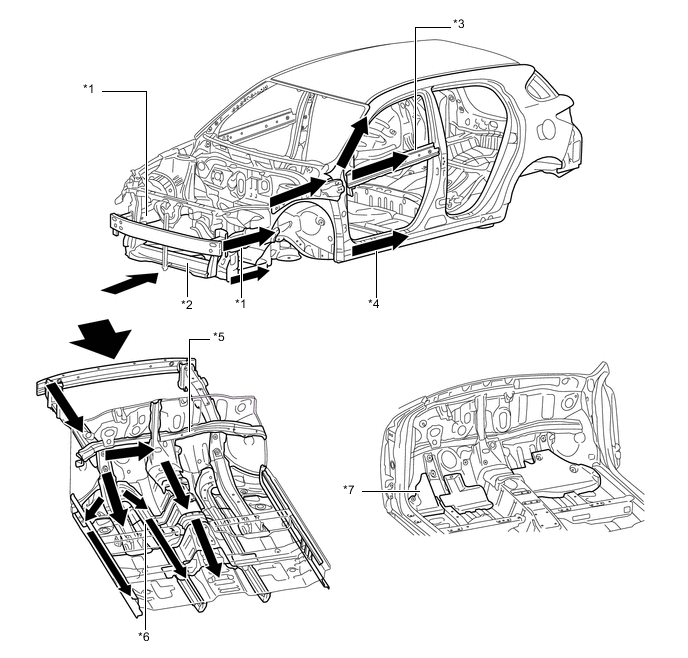
Text in Illustration *1 Front Side Member *2 Radiator Support *3 Door Beltline Reinforcement *4 Rocker Panel *5 Crossmember *6 Floor Member *7 Impact Absorbing Pad - - 
Impact Flow - -
-
-
Impact Absorbing Structure for Side Collision
-
Ultra high tensile strength steel is used for the center pillar outer reinforcement, center pillar hinge reinforcement, rocker panel inner reinforcement, rocker panel outer reinforcement and roof center reinforcement to ensure high strength.
-
Bulkheads are placed on both sides of the No. 1 and No. 2 floor cross members and center floor side crossmember to efficiently transmit impact load from the impact beam to the floor crossmembers.
-
The use of roof reinforcements enables a construction that transmits load to the opposite side of the vehicle in a collision.
-
Optimal placement of the impact protect beams enables a construction that efficiently transmits load.
-
The impact support box is optimally placed on the front floor between the driver seat and front passenger seat to ensure that load is transmitted from the center pillar to the seat pipe, impact support box, and seat pipe on the opposite side, thus helping secure sufficient survival space.

Text in Illustration *1 Center Pillar Outer Reinforcement *2 Center Pillar Hinge Reinforcement *3 Rocker Panel Outer Reinforcement *4 No. 1 Floor Crossmember *5 No. 2 Floor Crossmember *6 Center Floor Crossmember *7 Roof Reinforcement *8 Impact Protect Beam *9 Impact Support Box *10 Seat Pipe *11 Center Pillar - - Impact Flow - -
-
-
Impact Absorbing Structure for Rear Collision
-
Straight rear side members are used to reduce body deformation in a rear collision, and the reinforcements in rear side members have been optimally located to ensure high strength.
Text in Illustration *1 Rear Side Member *2 Barrier
-
-
Lessening Pedestrian Injury
-
Energy absorbing material has been adopted in front of the bumper reinforcement and under the radiator support, easing the impact to the pedestrian's legs to help reduce injuries.
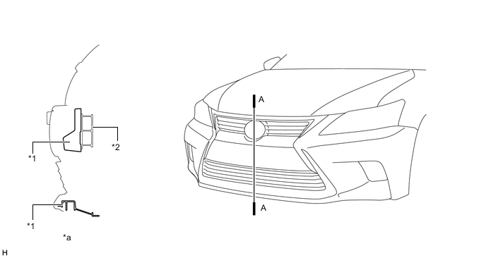
Text in Illustration *1 Energy Absorbing Material *2 Bumper Reinforcement *a A-A Cross Section - - -
A hood reinforcement is provided for the hood inner panel to help secure excellent pedestrian protection performance and tensile rigidity.
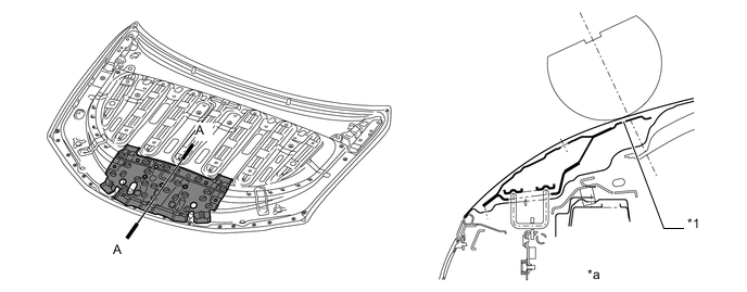
Text in Illustration *1 Hood Reinforcement - - *a A-A Cross Section - -
-
-
-
Aerodynamics
-
Aero Stabilizing Fin
-
Aero stabilizing fins are provided on the front passenger door, driver door and on each rear combination light lens for enhanced aerodynamics.
-
After passing the aero stabilizing fin, the air speed will increase and a vortex will be generated.
-
This vortex increases the speed of the surrounding air while at the same time pulling the airflow towards the vehicle body.
-
The airflow with higher speed passes near both sides of the vehicle body and ends at the rear of the vehicle. This helps to hold the vehicle body, and thus stabilizes the vehicle.
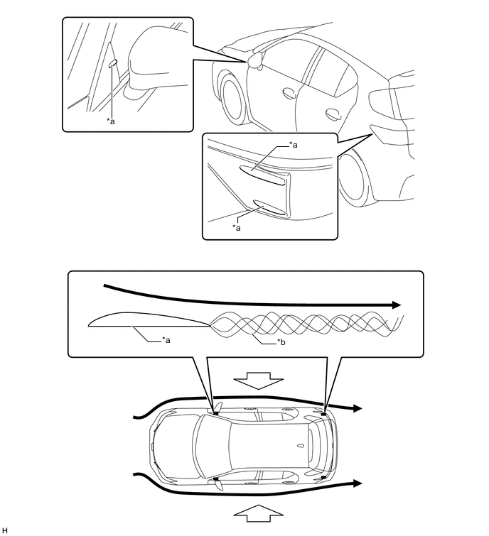
Text in Illustration *a Aero Stabilizing Fin *b Vortex Airflow 
Hold the Vehicle from Both Sides
-
-
Under Cover
-
Various types of airflow routing parts are provided under the floor to control airflow. In addition, an undercover is provided to make the under floor area flat in order to ensure excellent aerodynamic performance.
-
A fin-shaped floor under cover and rear under cover have been adopted to achieve higher diffuser efficiency, ensuring stability.
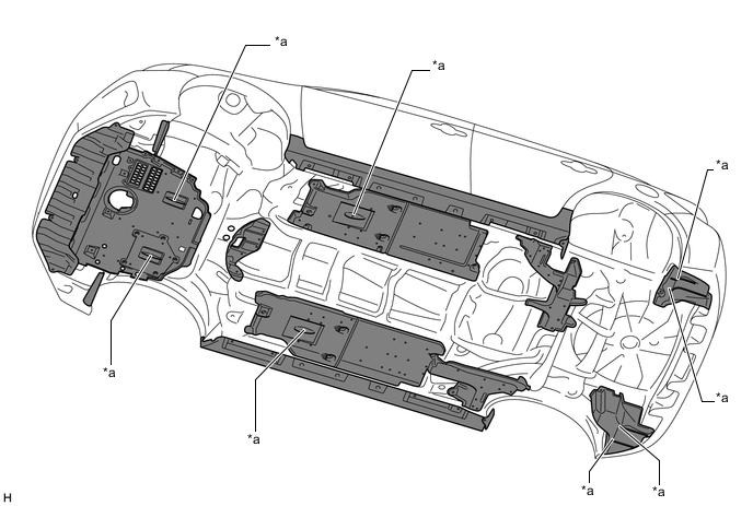
Text in Illustration *a Fin-shape - - 
Undercover Area - - -
-
Roof Spoiler
-
A roof spoiler with integrated high-mount stop light is available, realizing both excellent aerodynamic performance and an advanced design.
-
-
Cut-out Roof Spoiler (F SPORT)
-
A roof spoiler with cut-out is available, ensuring excellent aerodynamic performance and handling stability.
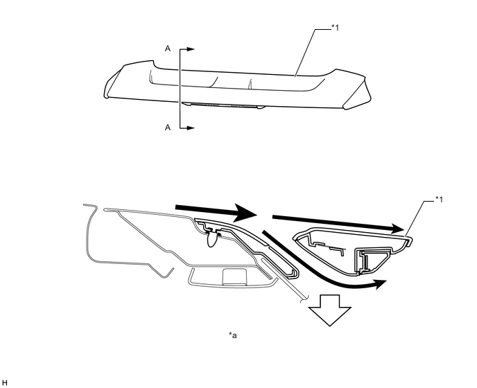
Text in Illustration *1 Rear Spoiler - - *a A-A Cross Section - - Airflow Down Force
-
-
-
-
CONSTRUCTION
-
Lightweight and Highly Rigid Body
-
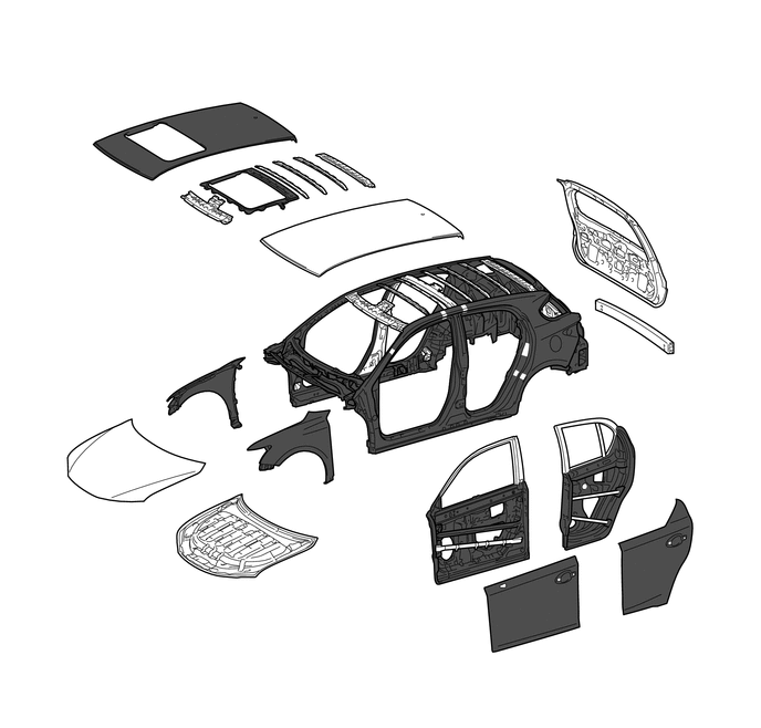
High strength steel is used in order to realize excellent body rigidity and a lightweight body.
-
Aluminum is used in the hood panel, front bumper reinforcement, back door and rear bumper reinforcement, resulting in a lightweight vehicle.
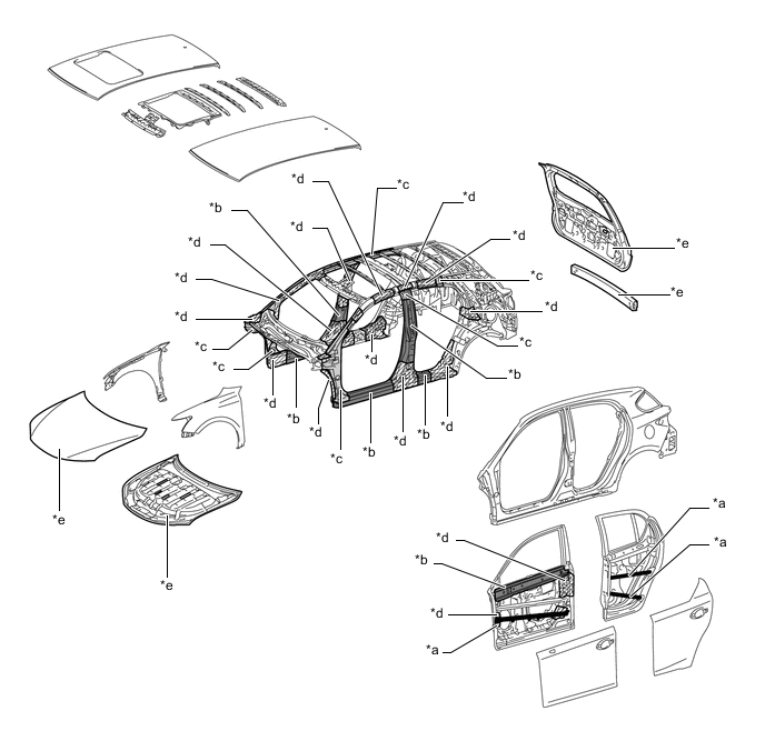
Text in Illustration (Upper Body:) *a High Strength Steel (1470 MPa Class) *b High Strength Steel (980 MPa Class) *c High Strength Steel (590 MPa Class) *d High Strength Steel (440 MPa Class) *e Aluminum - - 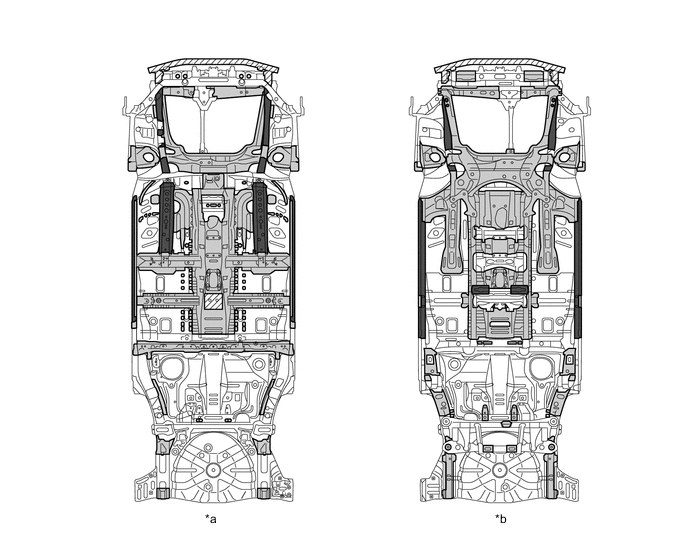
Text in Illustration (Under Body:) *a Top View *b Bottom View High Strength Steel (590 MPa Class) 
High Strength Steel (440 MPa Class) 
Aluminum - - -
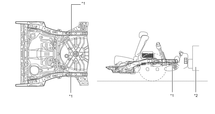
Braces have been adopted for the lower surfaces of the front and rear suspension members, realizing excellent rigidity.
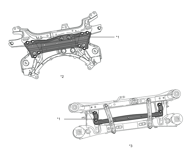
Text in Illustration *1 Brace *2 Front Suspension Member *3 Rear Suspension Member - -
-
-
Rust-resistant Body
-
Anti-corrosion steel sheet is used as shown in the following illustration:
Text in Illustration (Upper Body:) Anti-corrosion Steel Sheet - - 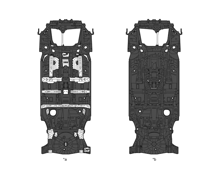
Text in Illustration (Under Body:) *a Top View *b Bottom View Anti-corrosion Steel Sheet - -
-
-
Low Vibration and Low Noise Body
-
The following items are provided to reduce vibration in the dash panel.
-
A dash panel crossmember
-
A tunnel reinforcement that connects both sides of the floor
-
A cowl to brace that connects the floor and cowl
-
-
A rigid floor and optimized rib placement are used to reduce floor panel resonance.
-
The following items are provided to minimize movement of the body shell to ensure quietness.
-
A rocker inner bulkhead
-
A straight No. 1 crossmember
-
Highly rigid joints between the rocker inner reinforcements and floor.
Text in Illustration *1 Dash Panel Crossmember *2 Tunnel Reinforcement *3 Cowl To Brace *4 Rib *5 Rocker Inner Bulkhead *6 No. 1 Crossmember *7 Rocker Inner Reinforcement - -
-
-
Damping coatings are provided, combining enhanced quietness and reduced weight.
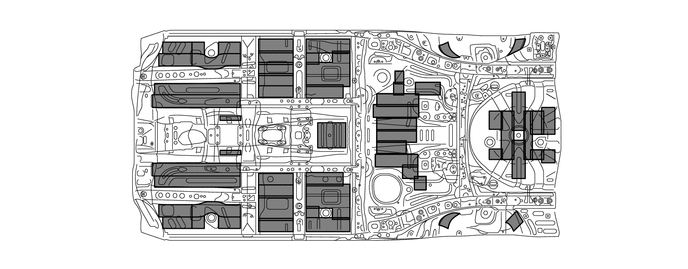
Text in Illustration Damping Coating - - -
An engine hood silencer, cowl silencer and dash panel outer silencer are provided to reduce the amount of engine noise that leaks into the cabin.
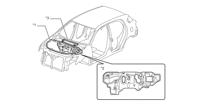
Text in Illustration *1 Engine Hood Silencer *2 Dash Panel Outer Silencer *3 Cowl Silencer - - -
Holes in the dash silencer have been filled, and the silencer has been expanded and thickened to reduce engine noise by reducing noise permeation from the engine compartment.
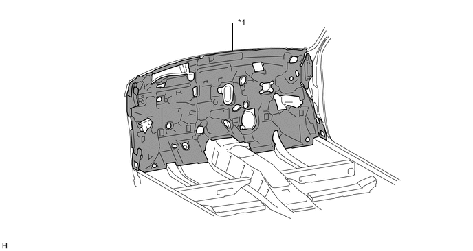
Text in Illustration *1 Dash Silencer - - -
The layout of the sound-absorbing material is optimized to reduce noise and vibration.
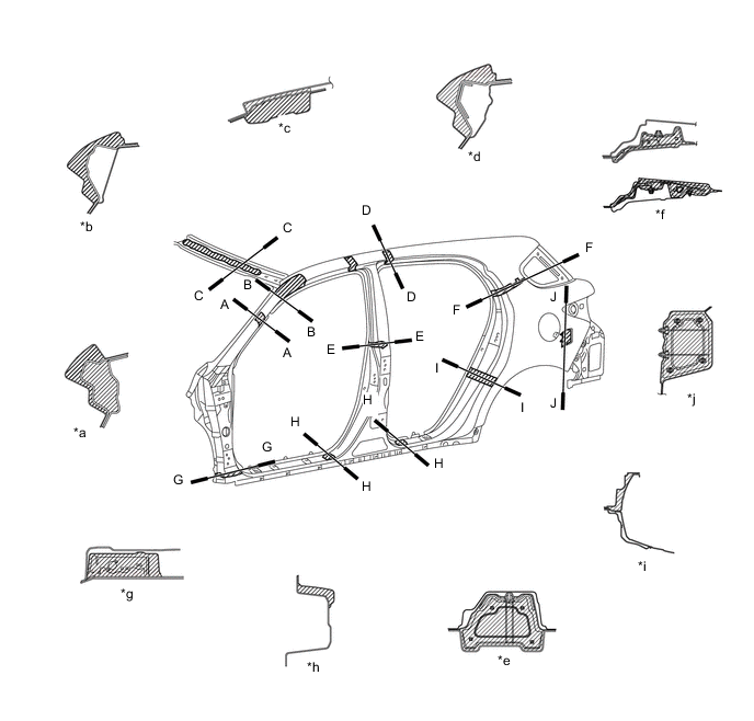
Text in Illustration *a A-A Cross Section *b B-B Cross Section *c C-C Cross Section *d D-D Cross Section *e E-E Cross Section *f F-F Cross Section *g G-G Cross Section *h H-H Cross Section *i I-I Cross Section *j J-J Cross Section Sound-absorbing Material - - -
Fender separators have been added to prevent noise from entering the cabin through the space between the fender and apron, ensuring a high level of quietness.
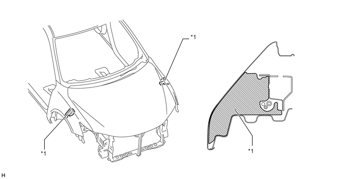
Text in Illustration *1 Fender Separator - - -
Sound absorbing material has been adopted for the rear wheel housing liner, absorbing road noise and ensuring quietness.
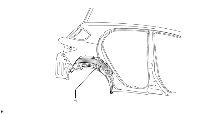
Text in Illustration *1 Rear Wheel Housing Liner - - Sound-absorbing Material - - -
Sound absorbing materials are adopted in the following areas in the cabin to reduce the amount of noise heard from both inside and outside the cabin.
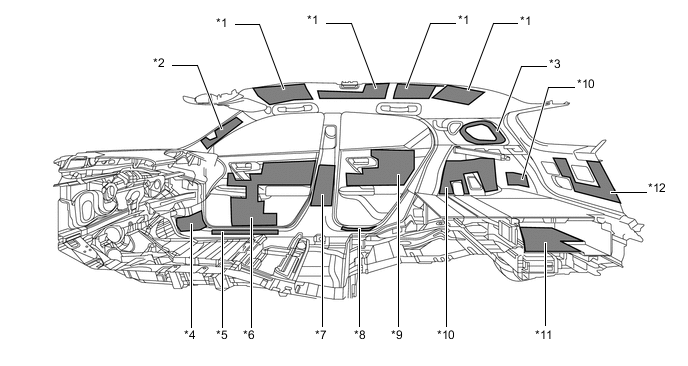
Text in Illustration *1 Roof Silencer *2 Front Pillar *3 Rear Pillar *4 Cowl Side Trim *5 Front Scuff Panel *6 Front Door Trim *7 Center Pillar Lower *8 Rear Scuff Panel *9 Rear Door Trim *10 Deck Side Trim *11 Deck Box *12 Back Door Trim Sound-absorbing Material - -
-
-
Parts with Low Repair Cost
-
A front side member bracket sub-assembly that absorbs impact energy to reduce damage to the body frame and the front bumper reinforcement sub-assembly are connected to the front side member using bolts to improve ease of repair and replacement.
-
The radiator support structure is connected to the front side members using bolts to improve the ease of repair, by reducing the damage to related parts (only the damaged parts need to be replaced).
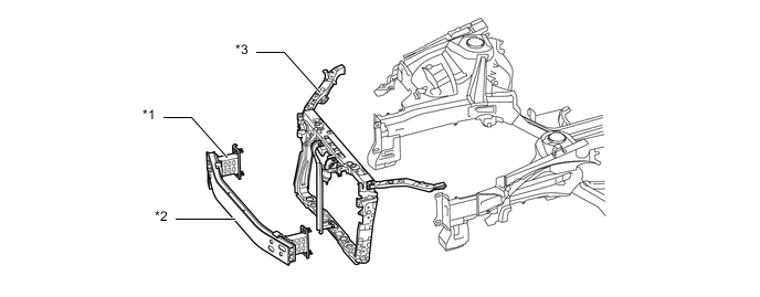
Text in Illustration *1 Crush Box *2 Bumper Reinforcement *3 Radiator Support - - -
The crush box is connected to the rear side member using bolts to improve the ease of repair and replacement.
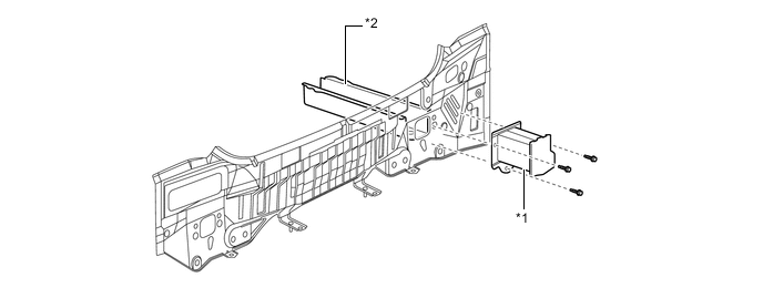
Text in Illustration *1 Crush Box *2 Rear Side Member
-
-