LIGHTING SYSTEM
-
FUNCTION OF MAIN COMPONENTS
-
Daytime Running Light System
Component Function Main Body ECU (Multiplex Network Body ECU) The main body ECU (multiplex network body ECU) receives various signals and illuminates the daytime running lights via the DRL relay. Engine Room Relay Block
-
DRL Relay
The DRL relay supplies power to the daytime running lights. Headlight Dimmer Switch Assembly
-
Light Control Switch
The light control switch outputs a light control signal and transmits it to the main body ECU (multiplex network body ECU). Parking Brake Switch Assembly The parking brake switch assembly outputs a parking brake operation signal to the main body ECU (multiplex network body ECU). Automatic Light Control Sensor The automatic light control sensor detects the ambient light level. -
-
Light Emitting Diode (LED) Headlight System (Models with LED Headlights)
Component Function Main Body ECU (Multiplex Network Body ECU) The main body ECU (multiplex network body ECU) receives the HEAD position signal from the light control switch and transmits a signal to the HEAD relay. Headlight Dimmer Switch Assembly
-
Light Control Switch
The light control switch transmits a HEAD position signal to the main body ECU (multiplex network body ECU). Engine Room Relay Block
-
No. 1 Integration Relay
The no. 1 integration relay supplies power to the LED driver modules. Headlight Assembly
-
LED Driver Module
-
The LED driver module keeps a constant level of direct current applied to the LED, achieving stable LED illumination.
-
The Light Emitting Diode (LED) light shines ahead over a broader area and further forward, increasing the area visible to the driver.
Combination Meter Assembly
-
Taillight Indicator Light
-
Master Warning Light
-
Multi-information Display
-
The taillight indicator light illuminates to inform the driver when the taillights are on.
-
The master warning light illuminates to inform the driver when a LED driver module detects a malfunction in the system.
-
The multi-information display displays a warning message to inform the driver when a LED driver module detects a malfunction in the system.
-
-
Manual Headlight Beam Level Control System
Component Function Headlight Leveling Switch The headlight leveling switch sends control signals to the headlight leveling motor. Headlight Dimmer Switch Assembly
-
Light Control Switch
The headlight dimmer switch assembly outputs a light control signal and transmits it to the main body ECU (multiplex network body ECU). Headlight Assembly LH/RH
-
Headlight Leveling Motor LH/RH
-
Based on the signals received from the headlight leveling switch, each motor moves the reflector in its headlight to vary its low beam angle.
-
Each headlight leveling motor uses a stepper type motor to precisely regulate the angle of the reflector.
Instrument Panel Junction Block Assembly
-
TAIL Relay
The TAIL relay supplies power to the headlight leveling motor. Main Body ECU (Multiplex Network Body ECU) The main body ECU (multiplex network body ECU) receives a HEAD position signal from the light control switch and transmits it to the headlight leveling ECU assembly. -
-
Automatic Headlight Beam Level Control System (Models with LED Headlights)
Component Function Headlight Leveling ECU Assembly
-
The headlight leveling ECU assembly detects changes of vehicle movement based on the rear height control sensor sub-assembly and vehicle speed signal.
-
The headlight leveling ECU assembly outputs control signals to the headlight leveling motors based on the detected value.
-
This ECU provides initial set control and a fail-safe function.
Headlight Assembly LH/RH
-
Headlight Leveling Motor LH/RH
-
Based on the signals received from headlight leveling ECU assembly, each headlight leveling motor moves the projector unit in the headlight to vary its angle.
-
Each headlight leveling motor uses a stepper motor to precisely regulate the angle of the projector unit.
Main Body ECU (Multiplex Network Body ECU) The main body ECU (multiplex network body ECU) receives a HEAD position signal from the light control switch and transmits it to the headlight leveling ECU assembly. Headlight Dimmer Switch Assembly
-
Light Control Switch
The light control switch transmits a HEAD position signal to the main body ECU (multiplex network body ECU). Rear Height Control Sensor Sub-assembly The rear height control sensor assembly LH detects vehicle movement and transmits a signal to the headlight leveling ECU assembly. Combination Meter Assembly
-
Automatic Headlight Beam Level Warning Light
-
The combination meter assembly transmits a vehicle speed signal to the headlight leveling ECU assembly.
-
The automatic headlight beam level warning light flashes to inform the driver when the headlight leveling ECU assembly detects a malfunction in this system.
-
-
Automatic Light Control System
Component Function Main Body ECU (Multiplex Network Body ECU) The main body ECU (multiplex network body ECU) receives various signals and illuminates the headlights, taillights, clearance lights, rear side marker lights and license plate lights. Engine Room Relay Block
-
No. 1 Integration Relay
-
DIM Relay
-
The no. 1 integration relay supplies power to the low beams.
-
The DIM relay supplies power to the high beams.
Instrument Panel Junction Block Assembly
-
TAIL Relay
The TAIL relay supplies power to the taillights, clearance lights, rear side marker lights and license plate lights. Automatic Light Control Sensor The automatic light control sensor detects the ambient light level. Headlight Dimmer Switch Assembly
-
Light Control Switch
The light control switch transmits an AUTO position signal to the main body ECU (multiplex network body ECU). Front Door Courtesy Light Switch Assembly (LH) The front door courtesy light switch assembly detects whether a door is open or closed and transmits a signal to the main body ECU (multiplex network body ECU). -
-
Light Auto Turn-off System
Component Function Main Body ECU (Multiplex Network Body ECU) The main body ECU (multiplex network body ECU) receives various signals and turns off the exterior lights. Engine Room Relay Block
-
No. 1 Integration Relay
-
DIM Relay
-
The no. 1 integration relay shuts off power to the low beams.
-
The DIM relay shuts off power to the high beams.
Instrument Panel Junction Block Assembly
-
TAIL Relay
-
FR FOG Relay*
-
The TAIL relay shuts off power to the taillights, clearance lights, rear side marker lights and license plate lights.
-
The FR FOG relay shuts off the power to the front fog lights.
Headlight Dimmer Switch Assembly
-
Light Control Switch
The light control switch transmits a light control position signal to the main body ECU (multiplex network body ECU). Front Door Courtesy Light Switch Assembly (LH) The front door courtesy light switch assembly detects whether a door is open or closed and transmits a signal to the main body ECU (multiplex network body ECU). *: Models with front fog lights
-
-
Door Mirror Foot Light System
Component Function Main Body ECU (Multiplex Network Body ECU) The main body ECU (multiplex network body ECU) receives various signals and illuminates the foot lights. Outer Mirror Control ECU Assembly (LH/RH) Receives request signals and illuminates the door mirror foot lights. Certification ECU (Smart Key ECU Assembly) The certification ECU (smart key ECU assembly) judges and certifies the ID code. Power Management Control ECU The power management control ECU receives the shift lever position signals from the shift lever position sensor (select sensor, shift sensor) and transmits them to the main body ECU (multiplex network body ECU).
-
Front Door Lock with Motor Assembly LH
-
Front Door Lock with Motor Assembly RH
-
Rear Door Lock with Motor Assembly LH
-
Rear Door Lock with Motor Assembly RH
The door unlock detection switch detects whether a door is locked or unlocked and transmits a signal to the main body ECU (multiplex network body ECU).
-
Front Door Courtesy Light Switch Assembly (LH)
-
Front Door Courtesy Light Switch Assembly (RH)
-
Rear Door Courtesy Light Switch Assembly (LH)
-
Rear Door Courtesy Light Switch Assembly (RH)
The courtesy switch detects whether a door is open or closed and transmits a signal to the main body ECU (multiplex network body ECU). Back Door Lock Assembly
-
Courtesy Light Switch
-
-
Emergency Brake Signal
Component Function Speed Sensors The speed sensors detect the wheel speed of each of the 4 wheels. Skid Control ECU (Brake Booster with Master Cylinder Assembly) The skid control ECU receives various signals and transmits an emergency brake signal to the stop light control ECU assembly. Yawrate Sensor The yawrate sensor outputs the acceleration information. Stop Light Switch Assembly The stop light switch assembly detects when the brake pedal is depressed. Stop Light Control ECU Assembly The stop light control ECU assembly blinks the stop lights while emergency stop light control is operating. Hazard Warning Signal Switch Assembly The hazard warning signal switch assembly transmits a hazard warning light on/off request to the skid control ECU. -
Automatic High Beam System
Component Function Forward Recognition Camera the forward recognition camera determines when to turn the high beams on and off after identifying the lights of oncoming vehicles, preceding vehicles and other lights from the picture information of its camera sensor. Then, the sensor sends high beam request signals to the main body ECU (multiplex network body ECU). Main Body ECU (Multiplex Network Body ECU)
-
Receives a switch on signal from the automatic high beam switch.
-
Receives an AUTO or head position signal and high beam position signal from the headlight dimmer switch assembly.
-
Receives the high beam request signal from the forward recognition camera and transmits a signal to H-LP SHADE relay.
Engine Room Relay Block
-
No. 1 Integration Relay
-
DIM Relay
-
The no. 1 integration relay supplies power to the low beams.
-
The DIM relay supplies power to the high beams.
Power Management Control ECU The power management control ECU outputs a signal to indicate that the shift position is in R. Based on this signal, the automatic high beam sensor (forward recognition camera) determines the direction of vehicle movement. Brake Booster with Master Cylinder Assembly
-
Skid Control ECU
The skid control ECU outputs information about the average speed of the 4 wheels. This information is used by the automatic high beam sensor (forward recognition camera) to control switching between the high and low beams of the automatic high beam system. Combination Meter Assembly
-
Illuminates the automatic high beam indicator light to inform the driver when the automatic high beam system is activated.
-
Illuminates the high beam indicator light to inform the driver when the high beams are on.
Yawrate Sensor The yawrate sensor outputs yawrate information. Automatic Light Control Sensor The automatic light control sensor detects the ambient light level and transmits a signal to the main body ECU (multiplex network body ECU). Automatic High Beam Switch The automatic high beam switch outputs the switch on signal to the main body ECU (multiplex network body ECU). Headlight Dimmer Switch Assembly The headlight dimmer switch assembly transmits the light control switch and dimmer switch signal to the main body ECU (multiplex network body ECU). -
-
Welcome Light Illumination System
Component Function Main Body ECU (Multiplex Network Body ECU) The main body ECU (multiplex network body ECU) receives various signals and illuminates the position lights, taillights and license plate lights. Instrument Panel Junction Block Assembly
-
TAIL Relay
The TAIL relay shuts off power to the taillights, position lights and license plate lights. Automatic Light Control Sensor The automatic light control sensor detects the ambient light level. Certification ECU (Smart Key ECU Assembly) The certification ECU (smart key ECU assembly) judges and certifies the ID code set from the door control receiver. -
-
Follow Me Home System (Models for Europe)
Component Function Main Body ECU (Multiplex Network Body ECU) The main body ECU (multiplex network body ECU) receives a light control signal and illuminates the headlights (low beams). Engine Room Relay Block
-
No. 1 Integration Relay
The no. 1 integration relay shuts off power to the low beams. Instrument Panel Junction Block Assembly
-
TAIL Relay
The TAIL relay shuts off power to the taillights, position lights and license plate lights. Headlight Dimmer Switch Assembly Light Control Switch The light control switch transmits a light control position signal to the main body ECU (multiplex network body ECU). -
-
-
OPERATING CONDITION
-
Daytime Running Light System
-
The daytime running lights illuminate when the following conditions are met:
-
The power switch is on (READY).
-
The low beams are not on.
-
The parking brake is off.
-
-
-
Light Auto Turn-off System
-
The light auto turn-off system operates as follows:
Function Operation Condition Headlight or Front Fog Light*1 Auto Turn-off*2 When all of the following conditions are met, the headlights or front fog lights*1 automatically turn off:
-
The power switch is turned off.
-
The headlight dimmer switch assembly is in the tail or head position.
-
The front fog light switch is on.*1
Exterior Light Auto Turn-off*2 When both of the following conditions are met, the exterior lights automatically turn off:
-
The power switch is turned off.
-
The headlight dimmer switch assembly is in the auto position.
Driver Door-linked*3 When all of the following conditions are met, the exterior lights automatically turn off:
-
The power switch is turned off or on (ACC).
-
The driver door is closed and then opened.
*1: Models with front fog lights
*2: Models for Europe
*3: Except models for Europe
-
-
-
Door Mirror Foot Light System
-
The door mirror foot light system operates as follows:
Function Operation Condition Actuation Area-linked When all of the following conditions are met, the foot lights automatically turn on:
-
The power switch is off.
-
All doors are closed.
-
The key is detected in the actuation area.
When the following condition is met, the foot lights automatically turn off:
The key is not detected in the actuation area.
Door Unlock-linked When all of the following conditions are met, the foot lights automatically turn on:
-
The power switch is off.
-
Any door is unlocked.
-
All doors are closed.
Door Lock-linked When one of the following conditions is met, the foot lights automatically turn off:
-
All doors are locked.
-
All doors are closed.
-
A door lock control switch outputs the lock signal.
Door-linked When the following condition is met, the foot lights automatically turn on:
Any door is opened and then closed.
Delay When approximately 15 seconds elapse after one of the following conditions is met, the foot lights turn off:
-
An actuation area-linked function is used.
-
The door unlock-linked function is activated.
-
Any door is opened and then closed.
Power switch-linked When the power switch is turned on (IG), the foot lights automatically turn off. -
-
-
Emergency Brake Signal
-
The activating and deactivating conditions for the emergency brake signal are as shown in the following table:
Condition Operation Condition Activating Conditions When all of the following conditions are met, the emergency brake signal starts operating:
-
Vehicle speed is above 55 km/h (35 mph).
-
Driver is depressing the brake pedal.
-
Emergency braking is detected from the vehicle deceleration.
Deactivating Conditions When any of the following conditions is met, the emergency brake signal stops operating:
-
Driver has released the brake pedal.
-
Emergency braking is no longer detected from the vehicle deceleration.
-
Driver has pressed the hazard warning signal switch.
-
-
-
Automatic High Beam System
-
The automatic high beam system operates as follows:
Function Operation Condition Active When all of the following conditions are met, the automatic high beam system is activated and the automatic high beam indicator light turns on:
-
The power switch is on (IG).
-
The light control switch (headlight dimmer switch assembly) is in the AUTO or HEAD position and the low beam headlights are on.
-
The dimmer switch (headlight dimmer switch assembly) is in the high beam position.
-
The automatic high beam switch is ON.
-
The shift is in any position other than R.
High Beams on When all of the following conditions are met, the automatic high beam system turns on the high beams after a short delay:
-
Vehicle speed is more than approximately 40 km/h (25 mph).*1
-
Vehicle speed is more than approximately 30 km/h (19 mph).*2
-
The area in front of the vehicle is dark.
-
No oncoming vehicles are present with the headlights on.
-
No preceding vehicles are present with the taillights on.
-
Few streetlights are present along the street ahead.
High Beams off When any of the following conditions is met, the automatic high beam system turns off the high beams after a short delay:
-
Vehicle speed is less than approximately 30 km/h (19 mph).*1
-
Vehicle speed is less than approximately 25 km/h (16 mph).*1
-
The area in front of the vehicle is not dark.
-
An oncoming vehicle with headlights on is detected.
-
A preceding vehicle with taillights on is detected.
-
Several streetlights are present along the street ahead.
*1: Models for Europe
*1: Except models for Europe
-
-
-
Welcome Light Illumination System
-
The welcome light illumination system operates as follows:
Function Operation Condition Door Unlock-linked When all of the following conditions are met, the position lights, taillights and license plate lights automatically turn on:
-
The power switch is off.
-
The headlight dimmer switch assembly is in the auto position.
-
The automatic light control sensor operation is performed.
-
A wireless door unlock operation or entry door unlock operation is performed.
Door Lock-linked When any of the following conditions are met, the position lights, taillights and license plate lights automatically turn off:
-
The power switch is turned on (IG).
-
The headlight dimmer switch assembly is not in the auto position.
-
A wireless door lock operation is performed.
-
An entry door lock operation is performed.
-
-
-
Follow Me Home System (Models for Europe)
-
The follow me home system operates if the lever of the headlight dimmer switch is pulled and released when both of the following conditions are met:
-
The power switch is off.
-
The headlight dimmer switch assembly is in the auto or off position.
-
-
-
-
FUNCTION
-
Automatic Headlight Beam Level Control System (Models with LED Headlights)
-
The automatic headlight beam level control system mainly consists of the headlight leveling ECU assembly, rear height control sensor assembly and 2 headlight leveling motors. The headlight leveling ECU assembly controls the system.
-
The headlight leveling ECU assembly detects the movement of the suspension from the rear height control sensor assembly LH and the vehicle speed from the combination meter assembly.
-
The headlight leveling ECU assembly then controls the headlight leveling motor based on this information, in order to change the headlight reflector angle.
-
When the headlight leveling ECU assembly detects that the vehicle is stopped and the power switch is on (READY), the ECU adjusts the stepper motors to their initial setting.
-
-
Automatic High Beam System
-
When passing an oncoming vehicle:
-
The automatic high beam system turns off the high beams before an oncoming vehicle comes within approximately 800 m (2625 ft.).
-
When an oncoming vehicle passes out of camera sensor range, the automatic high beam system turns the high beams on after a short delay.
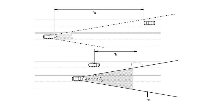
*a 800 m (2625 ft.) *b Delay *c Camera Sensor Angle - - Tech Tips
-
The detection distance varies depending on detected objects.
-
The timing of turning on and off the high beams varies depending on the intensity of oncoming (and preceding) vehicle lights.
-
-
When passing a preceding vehicle:
-
When approaching a preceding vehicle, the automatic high beam system turns off the high beams approximately 600 m (1969 ft.) before reaching it.
-
When a preceding vehicle passes out of camera sensor range, the automatic high beam system turns the high beams on after a short delay.
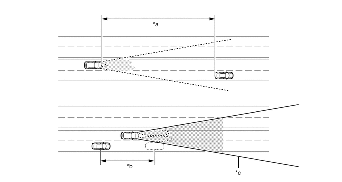
*a 600 m (1969 ft.) *b Delay *c Camera Sensor Angle - - Tech Tips
The timing of turning on and off the high beams varies depending on the intensity of the preceding vehicle lights.
-
-
-
-
CONSTRUCTION
-
LED Headlight
-
Through optimization of the shape of the lenses and reflectors inside the lights, a large illumination range has been realized.
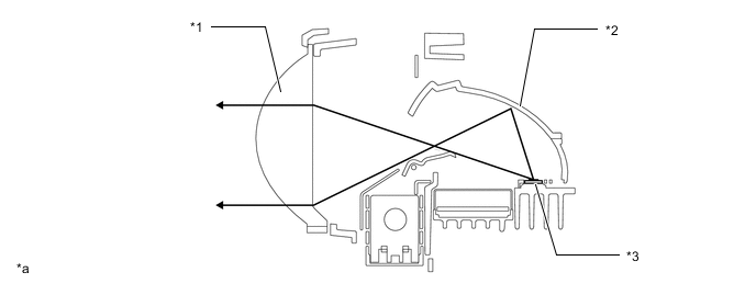
*1 Lens *2 Reflector *3 LED - - *a The illustration is for high beams. - -
-
-
Bi-Beam LED
-
When low beam is selected, the light source of the high beam headlight is blocked by the shade in the headlight assembly.
-
When high beam is selected, the shade turns so the light source of the high beam is not blocked.
-
The bi-beam LED is activated by the main body ECU (multiplex network body ECU). The main body ECU (multiplex network body ECU) receives as signal to turn on the high beams from the headlight dimmer switch assembly, then activates the built-in headlight actuator to slide the shade down.
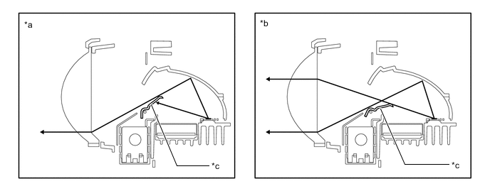
*a Low Beam *b High Beam *c Shade - -
-
-
LED Driver Module
-
When the light control switch is turned on, the LED driver modules immediately turn on the LEDs (approximately 0.1 seconds). In addition, by regulating the output current to the LEDs at a specified level, the LED driver modules prevent the light from getting brighter and dimmer due to voltage variation.
-
If a malfunction occurs in the LED headlight system, the LED driver module transmits a malfunction signal to the main body ECU (multiplex network body ECU). When the main body ECU (multiplex network body ECU) receives this malfunction signal, it transmits a signal to the combination meter assembly to warn the driver.
-
-
Forward Recognition Camera
-
The forward recognition camera consists of a Complementary Metal Oxide Semiconductor (CMOS) camera that receives images and a mirror portion that identifies light sources, and judges whether to use high beams or low beams.
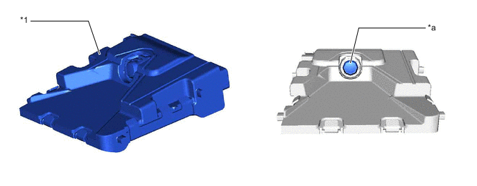
*1 Automatic High Beam Sensor (Lane Departure Warning Camera) - - *a Camera Portion - -
-
-
-
FAIL-SAFE
-
LED Headlight System
-
The LED driver modules operate the fail-safe functions listed below in accordance with the problem that has been detected.
Problem Outline Abnormal Input Voltage If the voltage that is input to LED driver module deviates from the normal operating voltage (10 to 16 V), the LED driver module stops illuminating the headlights. It resumes illuminating the headlights once the voltage returns to the operating voltage range. Abnormal Output (Open Circuit or Short Circuit) If an abnormal condition (open or short) occurs in the voltage that is output by a LED driver module, the LED driver module stops illuminating the headlights and will maintain this state until the power is reinstated. Power is reinstated by turning the headlight dimmer switch assembly (light control switch) from off to on.
-
-
Automatic Headlight Beam Level Control System (Models with LED Headlights)
-
If the headlight leveling ECU assembly detects a malfunction in the automatic headlight beam level control system, it will take the actions indicated in the table below.
Trouble Area System Operation Automatic Headlight Level Indicator Light Master Warning Light Headlight Leveling ECU Assembly Stops at current condition. - - Vehicle Speed Signal Continues control only when the vehicle is stopped. Flashes Illuminates Rear Height Control Sensor Assembly Signal
-
Stops control after returning to the initial position (If malfunction occurs at a position higher than the initial position).
-
Stops control at current condition (If failure occurs at a position lower than the initial position).
Flashes Illuminates Headlight Leveling Motor
-
Stops control after returning to the initial position (If malfunction occurs at a position higher than the initial position).
-
Stops control at current condition (If failure occurs at a position lower than the initial position).
Flashes Illuminates -
-
-
-
DIAGNOSIS
-
LED Headlight System
-
When the main body ECU (multiplex network body ECU) detects a malfunction in the LED headlight system, Diagnostic Trouble Codes (DTCs) are stored in memory.
-
DTCs can be read by using the Global TechStream (GTS). For details, refer to the Repair Manual.
-
-
Automatic Headlight Beam Level Control System (Models with LED Headlights)
-
When the headlight leveling ECU assembly detects a malfunction in the automatic headlight beam level control system, Diagnostic Trouble Codes (DTCs) are stored in memory.
-
DTCs can be read by using the Global TechStream (GTS). For details, refer to the Repair Manual.
-
-
Automatic Light Control System
-
When the main body ECU (multiplex network body ECU) detects a malfunction in the automatic light control system, Diagnostic Trouble Codes (DTCs) are stored in memory.
-
DTCs can be read by using the Global TechStream (GTS). For details, refer to the Repair Manual.
-
-
Automatic High Beam System
-
When the main body ECU (multiplex network body ECU) detects a malfunction in the automatic high beam control system, Diagnostic Trouble Codes (DTCs) are stored in memory.
-
The DTCs can be read using the Global TechStream (GTS). For details, refer to the Repair Manual.
-
-