WIPER AND WASHER SYSTEM
-
FUNCTION OF MAIN COMPONENTS
-
Wiper and Washer System
-
The wiper and washer system has the following parts and functions:
Component Function Windshield Wiper Switch Assembly
-
Outputs the position signal of the windshield wiper switch assembly to the front windshield wiper motor assembly, rear wiper motor assembly*1, front windshield washer motor and pump assembly, and rear washer motor and pump assembly*1, and windshield wiper relay assembly*2.
-
Setting this switch to AUTO will cause the rain sensing function to operate. This switch is also used to adjust the rain sensing function sensitivity.*2
Front Windshield Wiper Motor Assembly Activates the front wiper in accordance with the position signal of the front wiper switch (windshield wiper switch assembly) or the control signal from the windshield wiper relay assembly. Rear Wiper Motor Assembly (Built into Rear Wiper Relay)*1 Activates the rear wiper in accordance with the position signal from the rear wiper switch and rear washer switch (windshield wiper switch assembly). Front Windshield Washer Motor and Pump Assembly Activates the front windshield washer motor and pump assembly in accordance with the signal from the front washer switch (windshield wiper switch assembly). Rear Washer Motor and Pump Assembly*1 Activates the rear washer motor and pump assembly in accordance with the signal from the rear wiper switch and rear washer switch (windshield wiper switch assembly). Combination Meter Assembly*2 Outputs the vehicle speed signal to the windshield wiper relay assembly. Windshield Wiper Relay Assembly*2 Receives the operation signal from the windshield wiper switch assembly (front wiper switch and front washer switch) and the rain sensor, and inputs them into the front windshield wiper motor assembly. Rain Sensor*2 Senses rain when the front wiper switch (windshield wiper switch assembly) is in AUTO, and sends signals to the windshield wiper relay assembly. *1: Models with rear wiper and washer system
*2: Models with rain sensing function
-
-
-
Headlight Cleaner System
-
The headlight cleaner system has the following parts and functions:
Component Function Headlight Cleaner Switch Assembly The user operates this switch to operate the headlight cleaner system. Headlight Cleaner Motor and Pump Assembly Sends the washer fluid to the headlight cleaner in accordance with the signals from the headlight cleaner switch assembly. Headlight Cleaner Control Relay Receives the signals from the headlight cleaner switch assembly, front washer switch (windshield wiper switch assembly) and main body ECU, and controls the headlight cleaner motor and pump assembly. Main Body ECU (Multiplex Network Body ECU) Sends the headlight low beam illumination signal to the headlight cleaner control relay. Headlight Cleaner Actuator Sub-assembly The pressure of the washer fluid sent by the headlight cleaner motor and pump assembly pushes out the headlight cleaner washer nozzles. Headlight Cleaner Washer Nozzle Sprays the washer fluid sent by the headlight cleaner motor and pump assembly onto the headlights.
-
-
-
OPERATING CONDITION
-
Headlight Cleaner System
-
The headlight cleaner operates as follows:
Headlight Low Beam Headlight Cleaner Switch Assembly Front Wiper Switch (Windshield Wiper Switch Assembly) On On (First Time) On (Second Time or later) Turn On Activated Activated Not Activated Turn Off Not Activated Not Activated Not Activated
-
-
-
SYSTEM CONTROL
-
This system has the following functions.
Function Outline Wiper Forced Wiping*1 When any one of the following conditions is met while wiping is controlled by the rain sensing function, the windshield wiper relay assembly forcibly operates the wipers once.
-
The wiper switch is turned from OFF to AUTO when the power switch is on (IG).
-
The vehicle starts off.
-
The automatic control adjuster is turned to the + direction. (to boost the sensitivity)
Rain Sensing*1 Controls the wiping interval and speed in accordance with the amount of rain and vehicle speeds when the windshield washer switch assembly is in the AUTO position. Washer-linked Wiper with Drip-prevention*1 To prevent the fluid from dripping after the washer has been operated, this function operates the wipers once after they have operated in unison with the washer. Washer Headlight Cleaner*2 Sprays washer fluid on the headlight lenses to clean them. Washer Fluid Level Warning When the volume of washer fluid decreases to below a certain level, the combination meter warns the driver using a warning message on the multi-information display.
-
*1: Models with rain sensing function
-
*2: Models with headlight cleaner system
-
-
Rain Sensing Function
-
The rain sensing function controls the wiper timing in accordance with the amount of rain that strikes the windshield when the front wiper switch (windshield wiper switch assembly) is in the AUTO position.
-
The windshield wiper relay assembly circuit controls the timing based on the signal from the rain sensor.
-
-
Washer-linked Wiper with Drip-prevention Function
-
When the front wiper switch (windshield wiper switch assembly) is set to OFF or AUTO and the front washer switch (windshield wiper switch assembly) is turned on for approximately 0.2 seconds or more, the wipers start operating in LO at the same time as the washer fluid is sprayed.
-
The wipers operate 3 times in LO after the front washer switch (windshield wiper switch assembly) is turned off.
-
As shown in the following diagram, after the end of this operation, the wipers operate once more. They do so after an interval determined by the vehicle speed, so that any washer fluid drips are wiped away.
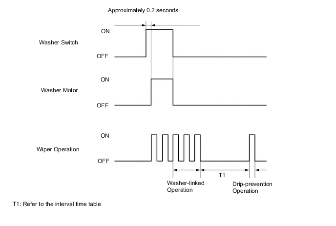
Interval Time Table Vehicle Speed km/h (mph) Interval Approximately 0 to 59 (0 to 37) Approximately 3 seconds Approximately 60 to 79 (37 to 49) Approximately 5 seconds Approximately 80 to 119 (50 to 74) Approximately 7 seconds Approximately 120 to 159 (75 to 99) Approximately 5 seconds Approximately 160 to 169 (99 to 105) Approximately 3 seconds Approximately 170 or more (106 or more) No operation
-
-
Headlight Cleaner System
-
When the power switch is on (IG), pressing the headlight cleaner switch assembly will cause the headlight cleaner motor and pump assembly to operate for a predetermined length of time.
-
When the power switch is on (IG) and the headlights are turned to low beam, pressing the front washer switch (windshield wiper switch assembly) once will cause the headlight cleaner motor and pump assembly to operate.
-
-
-
CONSTRUCTION
-
Rain Sensor
-
The rain sensor consists of a Light Emitting Diode (LED) that emits infrared rays, a photo diode that can receive those rays, a lens and rain sensor tape.
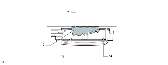
Text in Illustration *1 Rain Sensor Tape *2 Lens *3 Photo Diode *4 LED Tech Tips
If the rain sensor tape has been peeled off during a windshield glass replacement, make sure to affix new rain sensor tape. Failure to do so will lead to a system malfunction.
-
If no rain is present in the detection area, the infrared rays emitted by the LED are all reflected from the outer surface of the windshield glass and are received by the photo diode.
-
If rain is present in the detection area, a portion of the emitted infrared rays penetrates the windshield glass due to the change in the difference of the index of refraction between the glass and the area outside the windshield (difference between air and water). The ability of the windshield glass to reflect all light back inside changes due to the presence of rain. This change of internal reflection due to presence of water reduces the amount of infrared rays that are received by the photo diode. The amount of this reduction is then used to determine the amount of rain. Thus, this function controls the intermittent, low, and high operation in order to operate the wipers at an optimal wiping timing.
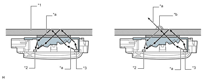
Text in Illustration *1 Windshield Glass *2 Photo Diode *3 LED - - *a Infrared Rays *b Rain Drop
-
-
Front Wiper Arm and Blade
-
A 650 mm (25.6 in.) wiper blade is installed on the driver side and a 450 mm (17.7 in.) wiper blade on the front passenger side, ensuring the sufficiently large wiping area.
-
A unified construction is used for the front wiper blades and arms. A fin-shaped resin cover is used for the entire wiper blade. This ensures the effectiveness of the wipers even when traveling at high speeds.
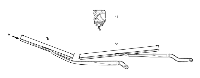
Text in Illustration *1 Fin-shaped Resin Cover - - *a View from A *b 450 mm (17.7 in.) *c 650 mm (25.6 in.) - -
-
-
Windshield Washer Nozzle
-
The diffuser type washer nozzles are located under the engine hood to ensure good appearance.
-
With the adoption of the diffuser type washer nozzles, only a smaller amount of washer fluid is needed to spread over a large area, realizing excellent wiping performance.
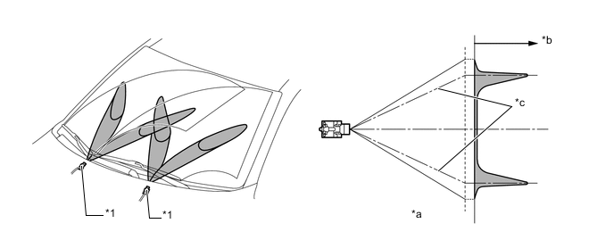
Text in Illustration *1 Windshield Washer Nozzle - - *a Top View of Distribution *b Fluid Volume *c Main Flow Center - - Tech Tips
Diffuser type washer nozzles cannot be adjusted because of their structure. Do not attempt to adjust the nozzles as it could damage them. If adjustment is necessary, adjust the spray pattern by replacing the nozzles with those selected from the 3 part numbers available. For details, refer to the Repair Manual.
-
-
Rear Washer Nozzle
-
A spray type rear washer nozzle is located on the back door panel.
-
The spray type washer nozzle spreads washer fluid over a large area, realizing excellent wiping performance.
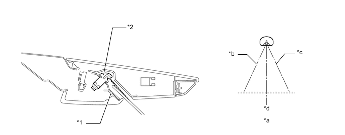
Text in Illustration *1 Back Door Panel *2 Rear Washer Nozzle *a Top View of Distribution *b Left of Main Flow Center *c Right of Main Flow Center *d Nozzle Center Axis
-
-
-
FAIL-SAFE
-
Rain Sensor
-
The following fail-safe measures are used when a malfunction is detected by the windshield wiper relay assembly (Models with rain sensing function):
Problem Outline Wiper Motor Malfunction Stops the operation of the rain sensing function Communication Signal Malfunction
-
Rain Sensor:
-
Continues performing the wiper operation that was occurring prior to occurrence of a malfunction.
-
Switches to the intermittent operation if a malfunction of the rain sensor is detected when the power switch is turned from off to on or the front wiper switch (windshield wiper switch assembly) is in the AUTO position.
-
Windshield Wiper Switch Assembly:
-
Continues performing the wiper operation that was selected prior to the occurrence of a malfunction.
-
-
-