AIRBAG SYSTEM
-
FUNCTION OF MAIN COMPONENTS
-
The main components of the airbag system have the following functions:
Component Function Airbag Sensor Assembly
-
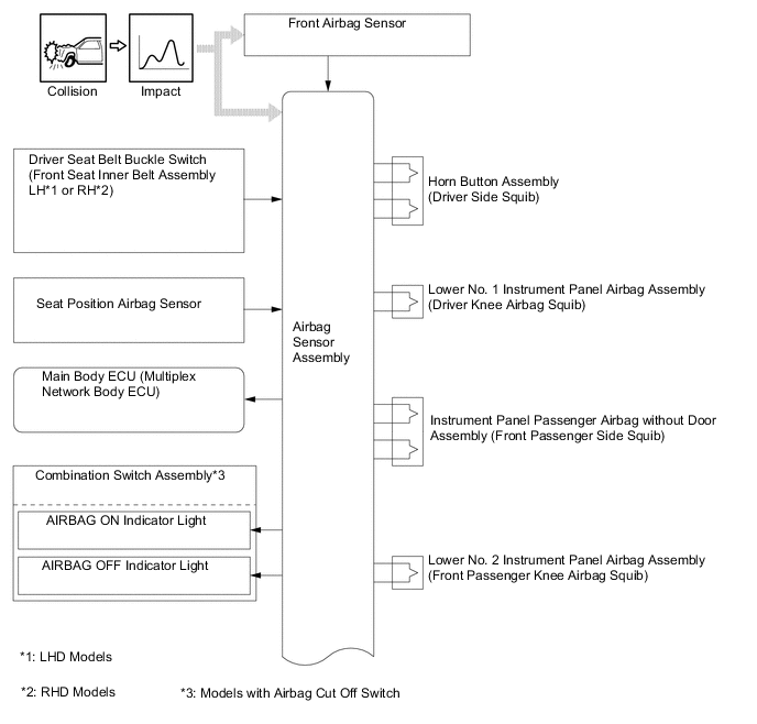
In the event of a frontal collision, the airbag sensor assembly receives the signal from either of the front airbag sensors. The airbag sensor assembly receives the signal via its judgment circuit and also receives another signal from the safing sensor built into the airbag sensor assembly. After receiving signals from the safing sensor and at least one of the front airbag sensors, the airbag sensor assembly determines whether the driver airbag, front passenger airbag, driver knee airbag, front passenger knee airbag and curtain shield airbags should be deployed, and the front seat belt pretensioners and rear seat belt pretensioners*1 should be activated. The airbag sensor assembly also diagnosis system malfunctions.
-
In the event of a side or rear side collision, the airbag sensor assembly receives signals from the side airbag sensor assembly or side No. 2 airbag sensor assembly. The airbag sensor assembly receives the side airbag sensor assembly or side No. 2 airbag sensor assembly signal via its judgment circuit and also receives another signal from the safing sensor built into the airbag sensor assembly. After receiving signals from the safing sensor and at least one of the side airbag sensor assembly or side No. 2 airbag sensor assembly, the airbag sensor assembly determines whether the front seat airbag and curtain shield airbag should be deployed, and the front seat belt pretensioner and rear seat belt pretensioner*1 should be activated. The airbag sensor assembly also diagnosis system malfunctions.
-
Sends the collision detection signal to the ECM through the Controller Area Network (CAN) via the power management control ECU to operate fuel pump control.
-
Sends the collision detection signal to the main body ECU (multiplex network body ECU) to operate the collision door lock release function.
-
Sends the collision detection signal to the power management control ECU to shut down the hybrid system power supply.
Horn Button Assembly Used as supplements to the seat belts to help reduce impact to the occupants. Instrument Panel Passenger Airbag without Door Assembly Lower No. 1 Instrument Panel Airbag Assembly Lower No. 2 Instrument Panel Airbag Assembly Front Seat Airbag Assembly LH/RH Curtain Shield Airbag Assembly LH/RH Spiral Cable with Sensor Sub-assembly Transmits ignition signals from the airbag sensor assembly to the SRS driver airbag. Front Airbag Sensor LH/RH Based on the deceleration of the vehicle during a frontal collision, distortion is created in the sensor and is converted into an electrical signal. Side Airbag Sensor Assembly LH/RH Based on the deceleration of the vehicle during a side collision, distortion is created in the sensor and is converted into an electrical signal. Side No. 2 Airbag Sensor Assembly LH/RH Based on the deceleration of the vehicle during a rear side collision, distortion is created in the sensor and is converted into an electrical signal. Seat Position Airbag Sensor Detects the slide position of the driver seat. Front Seat Outer Belt Assembly LH/RH Used to help reduce impact to the occupants. Rear Seat 3 Point Type Outer Belt Assembly LH/RH*1 Driver Seat Belt Buckle Switch (Front Seat Inner Belt Assembly LH*2 or RH*3) Detects if the driver seat belt is fastened. Airbag Cut Off Switch Cylinder Sub-assembly*4 Suspends the instrument panel passenger airbag without door assembly and lower No. 2 instrument panel airbag assembly operations. ECM Receives the collision detection signal from the airbag sensor assembly via the power management control ECU and stops to the fuel pump. Main Body ECU (Multiplex Network Body ECU) Receives the collision detection signal from the airbag sensor assembly and operates the collision door lock release function. Power Management Control ECU Receives the collision detection signal from the airbag sensor assembly during a collision and shuts down the hybrid system power supply by turning the System Main Relays (SMRs) off, in order to ensure safety. Combination Meter Assembly SRS Warning Light Turns on to alert the driver when the airbag sensor assembly detects a malfunction in the airbag system. Combination Switch Assembly*4 AIRBAG OFF Indicator Light Inform the occupants of the airbag cut off switch cylinder sub-assembly status. AIRBAG ON Indicator Light *1: Models with rear seat belt pretensioners
*2: LHD models
*3: RHD models
*4: Models with airbag cut off switch
-
-
-
OPERATING CONDITION
-
Ignition Condition
-
Deceleration sensors used for the airbag system are installed on various parts on the vehicle and calculate the deceleration (or acceleration) rate of each part during a collision.
-
Depending on the situation, the airbag sensor assembly sends a deployment signal to each airbag and pretensioner based on the information from each sensor.
-
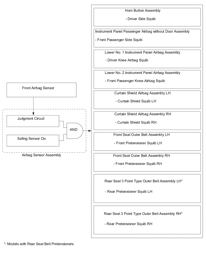
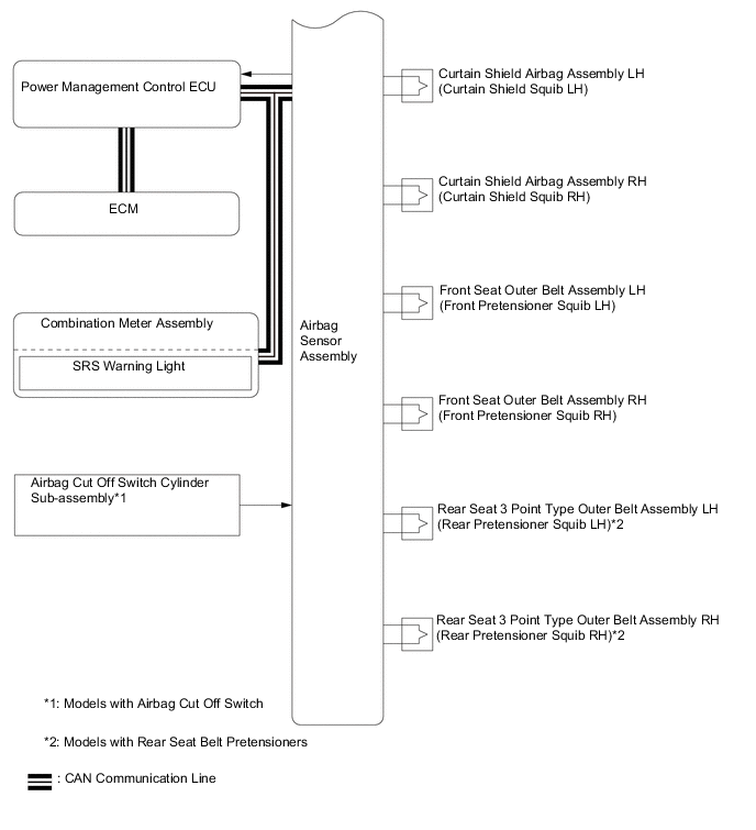
Frontal collision signals are produced based on the information from the airbag sensor assembly and front airbag sensors. Frontal collision signals are used to deploy all the airbags except the front side airbags and activate the front pretensioners and rear pretensioners* as indicated in the table below.
*: Models with rear seat belt pretensioners
Figure 1. Frontal Collision
-
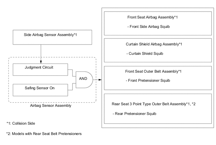
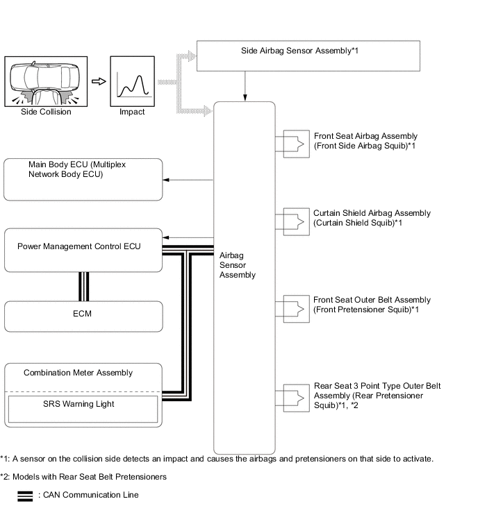
The front seat airbag assembly and curtain shield airbag assembly are deployed and the front pretensioner in the front seat outer belt assembly and rear pretensioner in the rear seat 3 point type outer belt assembly* are activated based on signals from the side airbag sensor assembly and airbag sensor assembly.
*: Models with rear seat belt pretensioners
Figure 2. Side Collision
-
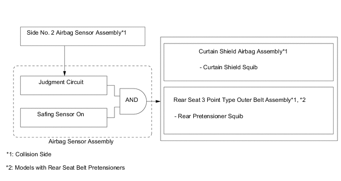
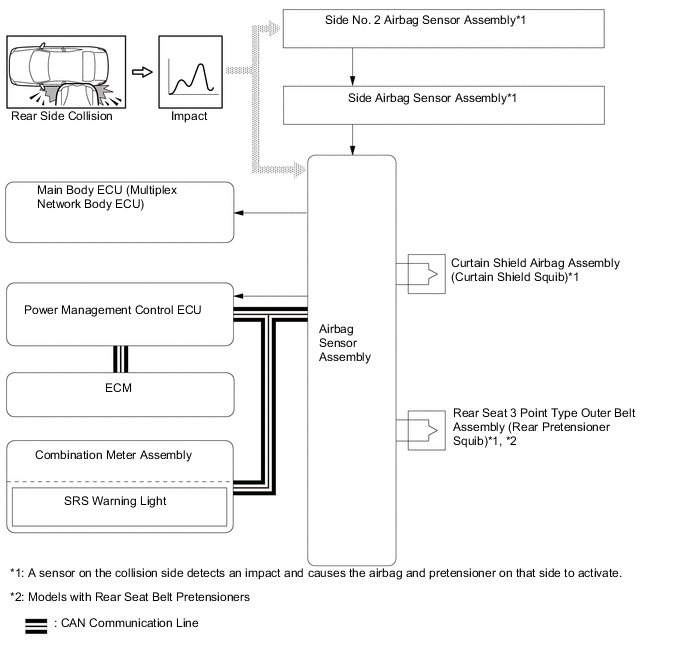
The curtain shield airbag assembly is deployed and the rear pretensioner in the rear seat 3 point type outer belt assembly is activated* based on signals from the side No. 2 airbag sensor assembly and airbag sensor assembly.
*: Models with rear seat belt pretensioners
Figure 3. Rear Side Collision
-
-
-
SYSTEM CONTROL
-
Airbag for Frontal Collision
-
There are 6 airbags which deploy in the event of a frontal collision: the horn button assembly, instrument panel passenger airbag without door assembly, lower No. 1 instrument panel airbag assembly, lower No. 2 instrument panel airbag assembly and curtain shield airbag assemblies. These airbags deploy simultaneously. The horn button assembly and instrument panel passenger airbag without door assembly use dual-stage control. In addition, each front pretensioner contained in a front seat outer belt assembly and each rear pretensioner contained in a rear seat outer belt assemby* are also activated.
*: Models with rear seat belt pretensioners
-
The airbag sensor assembly detects the information in the table below from various sources in order to activate the dual-stage control.
-
For a frontal collision, if a front airbag sensor detects an impact, it informs the airbag sensor assembly. The airbag sensor assembly causes the horn button assembly, instrument panel passenger airbag without door assembly, lower No. 1 instrument panel airbag assembly, lower No. 2 instrument panel airbag assembly and curtain shield airbag assemblies to deploy. Additionally, the airbag sensor assembly activates the seat belt pretensioners for the driver, front passenger and rear passengers*.
*: Models with rear seat belt pretensioners
Airbag Information Source Driver Extent of Impact
-
Front Airbag Sensor LH or RH
-
Airbag Sensor Assembly
Driver Seat Position Seat Position Airbag Sensor Seat Belt Condition Driver Seat Belt Buckle Switch (Front Seat Inner Belt Assembly LH*1 or RH*2) (Non-contact Type) Front Passenger Extent of Impact
-
Front Airbag Sensor LH or RH
-
Airbag Sensor Assembly
Occupant Classification*3 Airbag Cut Off Switch Cylinder Sub-assembly *1: LHD models
*2: RHD models
*3: Models with airbag cut off switch
-
-
-
Airbag for Side/Rear Side Collision
-
There are 2 airbags which deploy in the event of a severe side collision: the front seat airbag assembly and curtain shield airbag assembly. These airbags deploy simultaneously. Additionally, at the same time, the front seat belt pretensioner and rear seat belt pretensioner* are also activated.
*: Models with rear seat belt pretensioners
-
For a side collision, if the side airbag sensor assembly detects an impact, it informs the airbag sensor assembly, and the airbag sensor assembly causes the front seat airbag assembly and curtain shield airbag assembly to deploy simultaneously, and activates the front seat belt pretensioner and rear seat belt pretensioner*.
*: Models with rear seat belt pretensioners
-
For a rear side collision, if the side No. 2 airbag sensor assembly detects an impact, it informs the airbag sensor assembly via the side airbag sensor assembly, and the airbag sensor assembly causes the curtain shield airbag assembly to deploy simultaneously, and activates the rear seat belt pretensioner*.
*: Models with rear seat belt pretensioners
-
-
Airbag Cut Off Switch Cylinder Sub-assembly (Models with Airbag Cut Off Switch)
-
The airbag cut off switch cylinder sub-assembly can be used if deployment of the instrument panel passenger airbag without door assembly and lower No. 2 instrument panel airbag assembly are undesirable.
-
The airbag cut off switch cylinder sub-assembly can be operated by the mechanical key, which is supplied with the key. Once the airbag cut off switch cylinder sub-assembly is turned to OFF, the instrument panel passenger airbag without door assembly and lower No. 2 instrument panel airbag assembly will be disabled, regardless of any collision that may occurs.
-
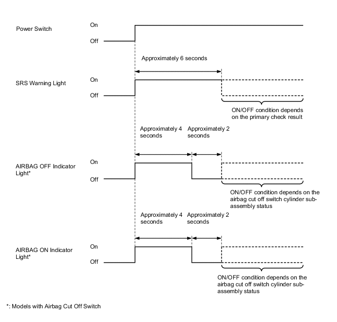
If the instrument panel passenger airbag without door assembly and lower No. 2 instrument panel airbag assembly have been disabled, the AIRBAG OFF indicator light in the combination switch assembly will illuminate to inform the driver.
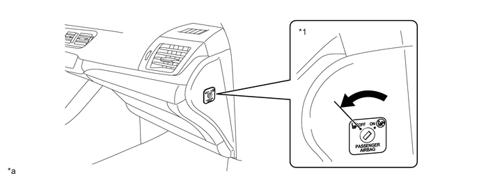
*1 Airbag Cut Off Switch Cylinder Sub-assembly - - *a The illustrations shown are examples only. - - -
The table below shows whether the airbag and seat belt pretensioner for the front passenger are enabled or disabled, and the AIRBAG ON/OFF indicator condition according to the airbag cut off switch cylinder sub-assembly status.
Item Airbag Cut Off Switch Cylinder Sub-assembly Status ON OFF Malfunction Front Passenger SRS Components Front Airbag ○ X X Knee Airbag ○ X X Seat Belt Pretensioner ○ ○ ○ AIRBAG ON/OFF Indicator Lights AIRBAG ON Indicator Light ON OFF OFF AIRBAG OFF Indicator Light OFF ON ON ○: Deploys or activates
X: Does not deploy or activate
-
-
Primary Check Illumination Control
-
After the power switch is turned on (IG), the airbag sensor assembly illuminates the SRS warning light in the combination meter assembly for approximately 6 seconds and conducts the primary check. During the primary check, the ignition of airbags is prohibited and a diagnosis of the airbag sensor assembly is performed. If a malfunction is detected during the primary check, the SRS warning light will remain on even after 6 seconds have elapsed.
-
After the power switch is turned on (IG), the airbag sensor assembly operates the passenger airbag ON/OFF indicator lights as shown below to check for an open in the indicator light circuits.
-
-
-
CONSTRUCTION
-
Airbag Sensor Assembly
-
The airbag sensor assembly consists of judgment circuit, a deceleration sensor, ignition control circuit, a safing sensor, backup power circuit, diagnostic circuit and memory circuit.
Item Outline Judgment Circuit Judgment circuits are built into the airbag sensor assembly to judge the severity of a collision using the acceleration/deceleration signals from the front airbag sensors, side airbag sensor assemblies and side No. 2 airbag sensor assemblies. Deceleration Sensor A deceleration sensor is built into the airbag sensor assembly. This sensor distorts in the event of a collision. The amount of distortion is based on the deceleration rate of the vehicle during a frontal collision and is converted into an electric signal. Ignition Control Circuit The ignition control circuit performs calculations based on the signal output from the judgment circuit of the airbag sensor assembly, front airbag sensors, side airbag sensor assemblies and side No. 2 airbag sensor assemblies. If the calculated values are greater than the specified values, the airbags are deployed. Safing Sensor During a frontal, side or rear side collision, this sensor turns on and outputs an on signal to the airbag sensor assembly if the deceleration rate of the safing sensor is greater than a specified value. Backup Power Circuit The backup power circuit consists of a power supply capacitor and a DC-DC converter. When the power supply to the airbag sensor assembly is disrupted during a collision, the power supply capacitor discharges and supplies electric power to the airbag system. The DC-DC converter operates as a boosting transformer when the auxiliary battery voltage falls below a predetermined level. Diagnostic Circuit The diagnostic circuit constantly monitors the system for malfunctions. When a malfunction is detected, it turns on the SRS warning light in the combination meter assembly to inform the driver. Memory Circuit When a malfunction is detected by the diagnostic circuit, a DTC is stored in memory.
-
-
Horn Button Assembly
-
The horn button assembly contains a bag and set of 2 initiators and propellants. The airbag sensor assembly helps optimize the airbag deployment rate by controlling the ignition timing of the initiators.
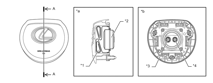
*1 Bag *2 Inflator *3 1st Initiator Connector *4 2nd Initiator Connector *a A-A Cross Section *b Reverse Side
-
-
Instrument Panel Passenger Airbag without Door Assembly
-
The instrument panel passenger airbag without door assembly contains a bag and set of 2 initiators and propellants. The airbag sensor assembly helps optimize the airbag deployment rate by controlling the ignition timing of these initiators.
-
When the instrument panel passenger airbag without door assembly is deployed, it forms the shape of 2 bags with a depression in the middle. Immediately after the airbag is deployed, the shape of 2 bags support the occupant on many planes, including the head and shoulders. Thus, this airbag disperses the load that is applied to the occupant in order to lessen the localized impact that is applied to the occupant immediately upon deployment.
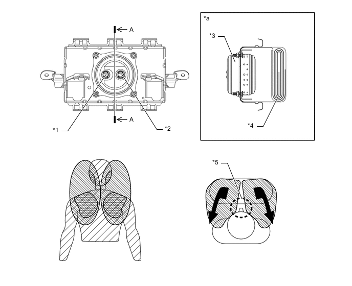
*1 1st Initiator Connector *2 2nd Initiator Connector *3 Inflator *4 Bag *5 Depression - - *a A-A Cross Section - -
-
-
Lower No. 1 Instrument Panel Airbag Assembly and Lower No. 2 Instrument Panel Airbag Assembly
-
The lower No. 1 instrument panel airbag assembly and lower No. 2 instrument panel airbag assembly consist of an airbag door, inflator and a bag.
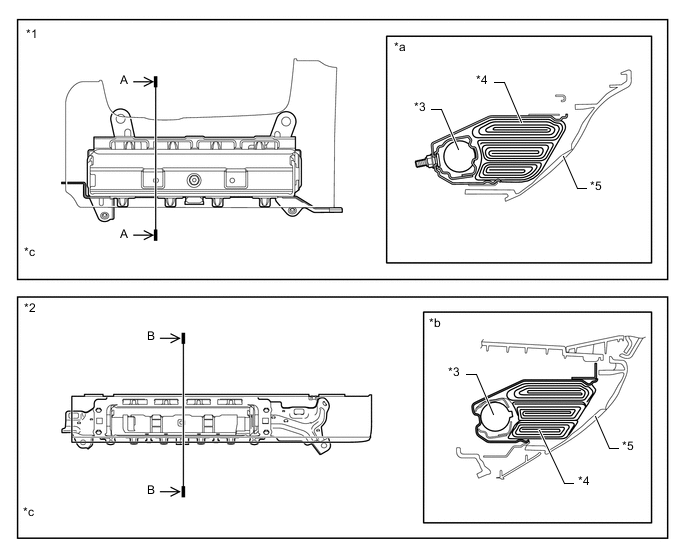
*1 Lower No. 1 Instrument Panel Airbag Assembly *2 Lower No. 2 Instrument Panel Airbag Assembly *3 Inflator *4 Bag *5 Airbag Door - - *a A-A Cross Section *b B-B Cross Section *c The illustrations shown are examples only. - -
-
-
Front Seat Airbag Assembly
-
Each front seat airbag assembly is a one-piece design, consisting of an inflator and a bag.
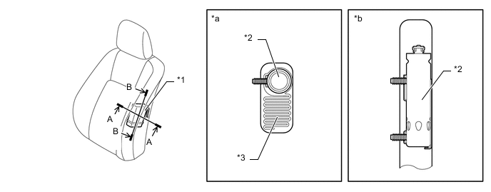
*1 Front Seat Airbag Assembly *2 Inflator *3 Bag - - *a A-A Cross Section *b B-B Cross Section
-
-
Curtain Shield Airbag Assembly
-
Each curtain shield airbag assembly is a one-piece design, consisting of an inflator and a bag.
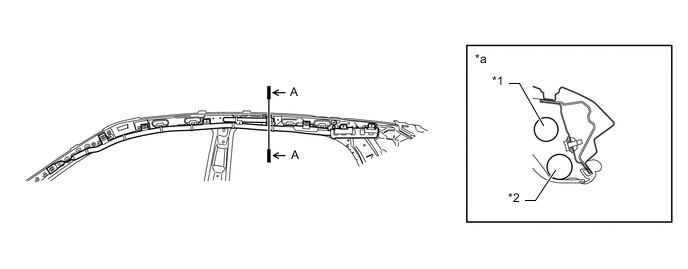
*1 Inflator *2 Bag *a A-A Cross Section - -
-
-
Front Airbag Sensor
-
The front airbag sensors are electrical type deceleration sensors. As a result of the deceleration of the vehicle during a frontal collision, distortion is created in the internal element in the sensor and is converted into an electrical signal.
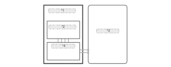
*1 Front Airbag Sensor *2 Deceleration Sensor *3 Airbag Sensor Assembly *4 Communication Circuit
-
-
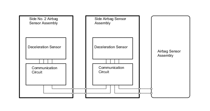
Side Airbag Sensor Assembly and Side No. 2 Airbag Sensor Assembly
-
A deceleration sensor is built into each side airbag sensor assembly and side No. 2 airbag sensor assembly. As a result of the deceleration of the vehicle during a side or rear side collision, distortion is created in the internal element in the sensor and is converted into an electrical signal.
-
-
Seat Position Airbag Sensor
-
The seat position airbag sensor, which uses a Hall IC, detects changes in magnetic flux that occurs due to the movement of the upper rail.
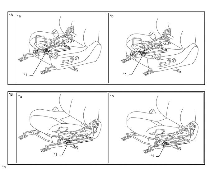
*A Models with Power Seat Control System *B Models without Power Seat Control System *1 Seat Position Airbag Sensor - - *a Seat position is rearward *b Seat position is forward *c The illustrations shown are examples only. - -
-
-
Driver Seat Belt Buckle Switch (Front Seat Inner Belt Assembly)
-
A non-contact type switch is built into the seat belt buckle switch (front seat inner belt assembly) on the driver side.
-
The non-contact type switch contains a MR IC and magnet.
-
The ejector inside the driver seat belt buckle switch (front seat inner belt assembly) and the plate installed to the ejector move when the seat belt is removed or inserted. The movement of the plate changes the magnetic flux density of the magnet.
-
The MR IC detects changes in magnetic flux density. These changes indicate that the seat belt is either fastened or unfastened, and the MR IC outputs a signal to the airbag sensor assembly.
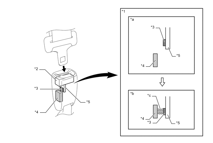
*1 Driver Seat Belt Buckle Switch *2 Ejector *3 Magnet *4 MR IC *5 Plate - - *a Seat belt not fastened *b Seat belt fastened *c Magnetic Flux - -
-
-
-
DIAGNOSIS
-
If the airbag sensor assembly detects a malfunction in the airbag system, the airbag sensor assembly illuminates the SRS warning light to alert the driver of the malfunction and stores the malfunction data in memory as Diagnostic Trouble Codes (DTCs).
-
The airbag sensor assembly outputs malfunction data and 5-digit Diagnostic Trouble Codes (DTCs) to the Global TechStream (GTS).
-
The 5-digit DTCs can be read by connecting the Global TechStream (GTS) to the DLC3. For details, refer to the Repair Manual.
-
If the SRS airbags deploy, the airbag sensor assembly will turn on the SRS warning light. However, unlike an ordinary malfunction, a DTC will not be stored. The SRS warning light cannot be manually turned off. It is necessary to replace the airbag sensor assembly with a new one.
-