TELEMATICS SYSTEM(for G-BOOK)
-
FUNCTION OF MAIN COMPONENTS
Component Function Type Cellular Phone Connection Telematics Transceiver Connection Bluetooth-compatible Cellular Phone Sends and receives the data and voice signals used for the G-BOOK system through a communication network. X - Tethering-compatible Cellular Phone or Mobile Wi-Fi Router Sends and receives the data used for the G-BOOK system through a communication network using Wi-Fi communication. X - Telephone Microphone Sends the microphone voice signal to the radio receiver assembly. X X
-
When the operator service is used: Sends the microphone voice signal to the radio receiver assembly.
-
When an emergency call is made: Sends the microphone voice signal to the telematics transceiver (data communication module).
- X Navigation Antenna Assembly Receives GPS radio waves and sends them to the radio receiver assembly. X X Transmits the vehicle location together with an emergency call. - X Roof Antenna Assembly Sends and receives the data and voice signals used for the G-BOOK system through a communication network. - X Emergency Call Switch When pressed, sends a switch signal to the telematics transceiver (data communication module).
(When a manual maintenance check or manual emergency call is performed.)
- X LED Indicator Light*1 Green
-
Turns on when the system is under a service contract and operating normally within the service area.
-
Blinks during a call or a maintenance check and turns off when the system is malfunctioning.
- X Red
-
Turns on when the vehicle is not within the service area.
-
Blinks when an emergency call or maintenance check has been aborted.
-
Turns off when the system is operating normally.
-
Blinks when in diagnostic mode to indicate a DTC.
- X Telematics Transceiver
(Data Communication Module)
-
Uses the roof antenna assembly to send and receive the data and voice signals used for the G-BOOK system through a communication network.
-
When the operator service is used: Sends a received voice signal to the radio receiver assembly.
-
When the operator service is used: Sends a sent voice signal from the radio receiver assembly to the roof antenna assembly.
-
When an emergency call is made: Sends a received voice signal to the vehicle speakers.
-
When an emergency call is made: Receives a sent voice signal from the telephone microphone assembly.
-
When an emergency call is made: Sends a mute signal to the stereo component amplifier assembly. (Mute function becomes active during the call.)
-
When an emergency call is made: Sends location information to the G-BOOK center.
- X Mayday Battery (Back-up Battery)
-
The mayday battery is a lithium manganese dioxide non-rechargeable battery.
-
Supplies power to the telematics transceiver (data communication module) to make an emergency call when the vehicle main battery is damaged in an accident.
-
Checks the battery condition and sends the self-diagnosis result to the radio receiver assembly via the telematics transceiver (data communication module).
-
When the telematics transceiver (data communication module) receives a Diagnostic Trouble Code (DTC) indicating that the mayday battery is malfunctioning, deteriorated or not compatible, the telematics transceiver blinks the red LED indicator light to inform the driver. The telematics transceiver will also store a DTC.
- X Radio Receiver Assembly
-
Uses a Bluetooth-compatible cellular phone to send and receive the data and voice signals used for the G-BOOK system through a communication network.
-
Sends and receives telematics data used for the G-BOOK system to and from the Bluetooth-compatible cellular phone using Bluetooth communication.
-
When the operator service is used: Sends the sent voice signal from the telephone microphone assembly to the Bluetooth-compatible cellular phone.
-
When the operator service is used: Sends the received voice signal from the Bluetooth-compatible cellular phone to the vehicle speakers.
-
Sends and receives telematics data used for the G-BOOK system to and from the tethering-compatible cellular phone or mobile Wi-Fi router using Wi-Fi communication.*2
X -
-
Sends and receives the data used for the G-BOOK system to and from the telematics transceiver (data communication module) using a telematics data signal.
-
When the operator service is used: Sends the sent voice signal from the telephone microphone assembly to the telematics transceiver (data communication module).
-
When the operator service is used: Sends the received voice signal from the telematics transceiver (data communication module) to the amplifier assembly using a AVC-LAN communication signal.
-
Periodically sends vehicle location information to the telematics transceiver (data communication module).
-
When a warning comes on, the radio receiver assembly receives a signal indicating the failure or malfunction of a system from the combination meter assembly via CAN communication and the telematics transceiver (data communication module) sends it to the G-BOOK center.
-
When the theft deterrent system is activated, the telematics transceiver (data communication module) sends a signal to the G-BOOK center indicating that the security horn has sounded.
- X Multi-display Assembly Displays signals received from the radio receiver assembly. X X Remote Touch Transmits signals from its switch knob, seesaw switch, and various other switches to the radio receiver assembly. X X Steering Pad Switch Assembly Sends operation signals from switches such as volume switch, mode switch, voice switch operation to the spiral cable with sensor sub-assembly. X X Spiral Cable with Sensor Sub-assembly Sends operation signals from the steering pad switch assembly to the radio receiver assembly. X X Main Body ECU (Multiplex Network Body ECU) Sends a security horn sounding signal to the radio receiver assembly when the theft deterrent system is activated. - X Airbag Sensor Assembly Sends an activation signal to the telematics transceiver (data communication module) when the airbags deploy.
(An automatic emergency call is made.)
- X Stereo Component Amplifier Assembly Receives a received voice signal sent from the radio receiver assembly as a MOST signal and outputs it as sound from the vehicle speakers. (When the operator service is used.) X X X: Used
-: Not used
*1: The green and red indicator lights turn on for 5 seconds immediately after the power switch is turned on (ACC).
*2: While Wi-Fi communication is used
-
-
FUNCTION
-
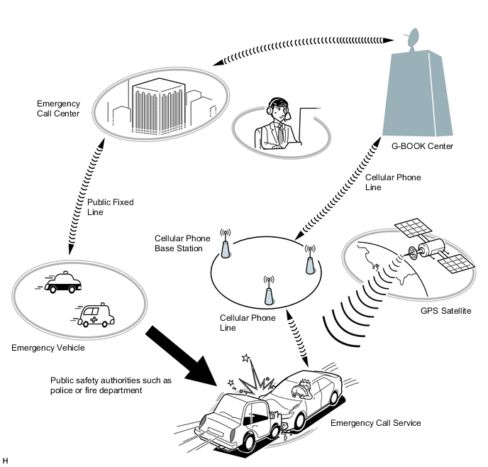
Emergency Call Service
-
The emergency call service automatically makes a call to a G-BOOK center operator in the event of an accident, such as one that makes the airbags deploy, in order to support prompt attendance by emergency personnel.
-
In the event of trouble such as an accident or sudden illness, the telematics transceiver (data communication module) can be used to call the emergency call center and send location information and the registered user information.
-
The emergency call service can be activated either manually or automatically to contact the G-BOOK center.
Call Method Operation Condition Automatic Call An automatic call is made in the event of an accident, such as one that makes the airbags deploy. The call occurs regardless of the condition of the occupants. Manual Call In the event of a sudden illness or an accident that does not cause the airbags to deploy, a manual call can be made by pressing the emergency call switch in the overhead console.
(To press the emergency call switch, the emergency call switch cover needs to be removed.)
-
The emergency call service operation and contract conditions can be confirmed by accessing the G-BOOK center and performing the following maintenance checks.
Maintenance Check Outline Automatic Maintenance Check The telematics transceiver (data communication module) automatically and periodically accesses the emergency call center to confirm if the user is still registered. Manual Maintenance Check The user can press the emergency call switch for 10 seconds or more while the green and red indicator lights are on immediately after the power switch is turned on (IG) to access the G-BOOK center and confirm that they are still registered. Tech Tips
In the following cases, the emergency call service may not be available or the service quality may suffer.
-
The G-BOOK online service has not been established or the first manual maintenance check has not been completed.
-
Communication is interrupted due to a malfunction of the telematics transceiver (data communication module) or any other related device.
-
The location cannot be determined.
-
Communication is interrupted due to a service provider system malfunction.
-
Communication problems occur in the communication network used for the emergency call system.
-
The emergency call service is suspended or halted due to emergency call provider reasons.
-
Although a manual call is made, the situation cannot be confirmed because the user cannot respond to questions from the G-BOOK center.
-
-
-
Theft Tracking Service
-
The theft tracking service notifies the G-BOOK center that the alarm has operated when the theft deterrent system is activated.
-
The G-BOOK center makes a call to the user to notify them that the alarm has operated. If the call cannot get thorough, the G-BOOK center sends a short message service (SMS) message.
-
In the event of theft, the vehicle location can be tracked as requested by the user. If requested by the user, a G-BOOK operator asks the authorities to find the stolen vehicle and take the case under their control.
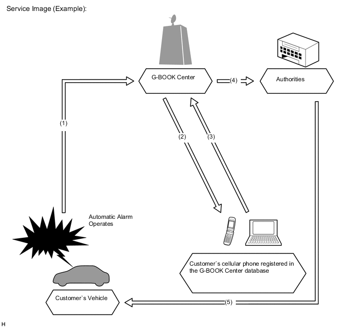
No. Process of alarm notification (1)
-
Trouble occurs and the automatic alarm operates.
-
The vehicle location is confirmed.
(2) The user is notified about the trouble by a call. If the call cannot get through, the user is notified by a short message service (SMS) message. (3) The user makes a request. (4) A call-out is made to the authorities. (5) The authorities respond to the scene. -
-
-
Remote Maintenance Service
-
Remote maintenance mail and warning notifications are provided as the remote maintenance service.
Contents Outline Remote Maintenance Mail
-
The remote maintenance mail is sent by the telematics transceiver (data communication module) to the G-BOOK center to provide information about the condition of the vehicle.
-
The G-BOOK center then notifies the vehicle user about the inspection timing and maintenance notice.
Warning Notification
-
The warning notification is a signal indicating a failure or malfunction of systems, information about which is received by the combination meter assembly.
-
This notification is sent by the telematics transceiver (data communication module) to the G-BOOK center when the power switch is on (Start).
-
The G-BOOK center then notifies the vehicle user about the malfunction condition and how to cope with the problem based on the information received.
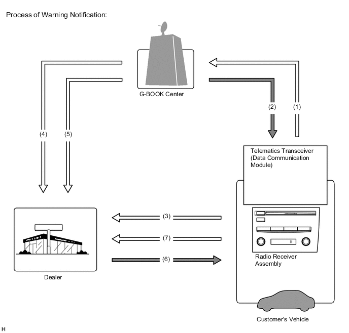
No. Process of Warning Notification (1) Information about the vehicle, details of any trouble or malfunctions, is sent. (2) The user is notified about the malfunction and how to cope with it. (3) The user requests a reservation. (4) Location and membership information. (5) Information about a failure or malfunction. (6) The reservation has been confirmed. (7) The user brings the vehicle in. -
-
-
Operator Service
-
The operator service allows the user to directly call a G-BOOK center operator. The user can ask the operator to set a destination or send a POI facility search result or news and weather forecasts information to the navigation system.
-
The operator service uses the radio receiver assembly to make calls via the following devices.
-
Cellular phone connection type navigation system: Cellular phone. It is necessary to register the phone using the Bluetooth hands-free function.
-
Telematics transceiver connection type navigation system: Telematics transceiver (data communication module). It is not necessary to register a phone using the Bluetooth hands-free function.
Function Outline Destination Setting Displays the specified destination location on the navigation system screen. Weather Forecast* Displays and reads out the vehicle location, destination or weather forecast for the specified area. News* Displays and reads out updates, society, sports and entertainment news.
-
*: Using the browser content display function built-in the navigation system, the following contents can be displayed. If news content is displayed, headlines are read out to assist the driver in checking the content easily even while driving.
-
-
-
Navigation System Link Function
-
The navigation system link function provides the navigation system with real-time information obtained from the G-BOOK center, offering more effective use of the navigation system for the user.
-
The navigation system link function has the following functions:
Function Outline G Route Search Searches for the most suitable route to the destination based on information about wide-area traffic congestion prediction. Partial update of map database Partially updates map data in the navigation system by obtaining new road data or main POI data surrounding the current position or destinations from the G-BOOK center. Searching for POIs on the WEB Transfers POI information, which was searched for on the Mapbar site, to the navigation system. A found POI can be set as a destination or registered as a G-memory point. G-memory Point
-
When a POI is searched for using the contents of G-BOOK.com or a website, it can be registered as a G-memory point of the memory points in the navigation system.
-
By registering POIs as a G-memory point, a list of G-memory points can be displayed without connecting to the G-BOOK center.
-
-
-
Other Function
-
The G-BOOK system provides other functions in consideration of improving usability.
-
The other function is as follows:
Function Outline MY Request Content which is frequently searched for, such as news or weather forecast information, can be registered. After registration, information can be obtained through a simple operation.
-
-
-
CONSTRUCTION
-
Emergency Call Switch
-
The emergency call switch is available for the user to make a manual emergency call in the event of a sudden illness or an accident that does not cause the airbags to deploy.
-
The emergency call switch has an indicator light on the panel so that the user can confirm the operation of the system.
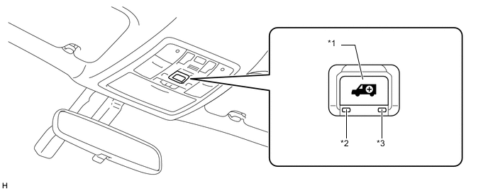
Text in Illustration *1 Emergency Call Switch *2 Emergency Call Switch Green Indicator *3 Emergency Call Switch Red Indicator - -
-
-
Indicators shown in each condition are as follows:
Indicator Light Operation Condition Green Red ON OFF The system is operating (the vehicle is within the cellular phone service area). OFF ON
-
The system is operating (the vehicle is outside the cellular phone service area).
-
A related device is malfunctioning (if the vehicle is within the cellular phone service area).
Blinks OFF
-
An emergency call is being performed.
-
A manual maintenance check is being performed.
OFF Blinks
-
An emergency call has failed.
-
An automatic maintenance check has failed (the vehicle is outside the cellular phone service area).
-
A manual maintenance check has failed.
-
A related device is malfunctioning.
ON ON
-
The power switch is turned on (IG).
-
If the indicator lights remain on for 5 seconds or more, a related device is malfunctioning.
OFF OFF
-
The G-BOOK service contract was not renewed.
-
The power switch is off.
-
A related device is malfunctioning.
-
The first manual maintenance check has not been completed.
-
-
-
DIAGNOSIS
-
For details on the procedure required to enter the Service Menu screen, refer to the Repair Manual.
-