FRONT SUSPENSION SYSTEM
-
CONSTRUCTION
-
Front Suspension Support Sub-assembly and Front Coil Spring
-
An integrated input construction type front suspension support sub-assembly is used.
-
All the inputs (from the front shock absorber assembly, front spring bumper, and front coil spring) are transmitted from the strut bearing via the suspension upper support to the body.
-
A pigtail type front coil spring is used where the top and bottom diameters are different, creating a compact and lightweight construction. The front coil springs are designed to oppose lateral force to reduce the bending force applied to the front shock absorber assembly. This reduces suspension friction, realizing a very comfortable ride.
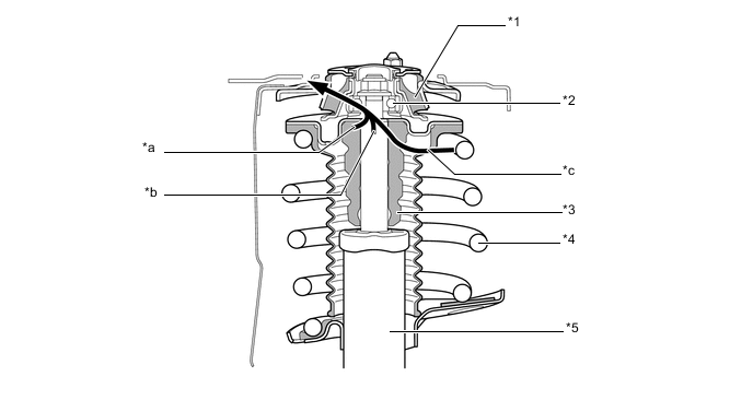
Text in Illustration *1 Front Suspension Support Sub-assembly *2 Strut Mounting Bearing *3 Front Spring Bumper *4 Front Coil Spring *5 Front Shock Absorber Assembly - - *a Front Spring Bumper Input *b Front Shock Absorber Assembly Input *c Front Coil Spring Input - -
-
-
Front Shock Absorber Assembly
-
Damping characteristics during low speed driving have been changed, enhancing comfort. (Models with 16-inch or 17-inch wheels)
-
The damping ratio during extension and compression has been increased on the extension side, helping prevent the wheels on the inside of a turn from lifting. Additionally, movement of the sprung mass on somewhat rough roads has been reduced and inputs from the road surface controlled, realizing a high level of handling stability and ride comfort. (F SPORT)
-
In the front shock absorber assembly, a low-pressure N2gas sealed type construction is used to suppress cavitations and a multi-leaf type linear control valve is also used to attain linear damping force characteristics, offering both driving stability and ride comfort.
Note
To prevent hazardous conditions, make sure to empty the gas from the shock absorber before discarding an N2gas sealed shock absorber. For details, refer to the Repair Manual.
-
Since the multi-leaf type linear control valve has a laminate-structure backing valve, it enables the damping force to be generated at lower piston speeds, compared with a structure that generates the damping force with only the base valve when compression force is applied.
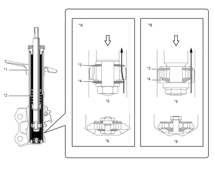
Text in Illustration *A Eco and Base Grade *B F SPORT *1 Low-pressure N2Gas
*2 Rebound Spring *3 Backing Valve *4 Inner Valve *5 Multi-leaf Type Linear Control Valve *6 Base Valve 
Oil Flow 
Compression Force -
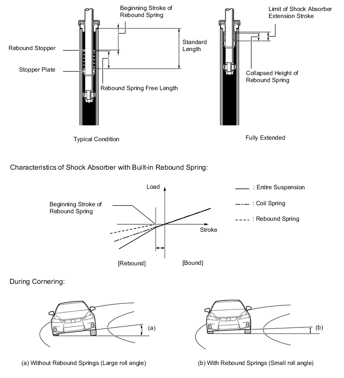
The built-in rebound spring is designed to function with the suspension spring in order to restrain suspension extension during rebound. Also, in order to realize a soft and comfortable ride, only the suspension springs are used when the suspension stroke is small during normal driving. However, when cornering, load is removed from the inner wheels, the functions of both the rebound spring and the suspension spring interact and the extension of the suspension is restrained. As a result, the vehicle has excellent maneuverability and stability.
-
-
Front Lower Suspension Arm Sub-assembly
-
An L-shaped front lower No. 1 suspension arm sub-assembly, of which the cross section structure is closed, has been provided. As a result, in addition to the material thickness having been made thinner, the cross section and arm shape have been optimized, thus, achieving both a light weight and high rigidity at the same time.
-
Along with the use of wider treads, the length of the front lower No. 1 suspension arm sub-assembly has been extended.
-
The installation point of the lower arm bush and the bushing characteristics have been optimized to achieve excellent ride comfort and steering characteristics.
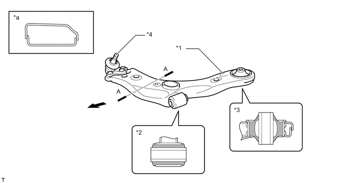
Text in Illustration *1 Front Lower No. 1 Suspension Arm Sub-assembly *2 Front Lower No. 1 Arm Bush (Cross Section) *3 Front Lower No. 2 Arm Bush (Cross Section) *4 Front Lower Ball Joint Assembly *a A-A Cross Section - - Front - -
-
-
Front Stabilizer Bar
-
The front stabilizer bar is hollow to achieve weight reduction. A ball joint is used between the front stabilizer link assembly and the front stabilizer bar, and between the front stabilizer link assembly and the front shock absorber assembly. This helps reduce suspension friction and increase link rigidity. As a result, the ball joints perform effectively even for small amounts of roll and maintain roll stability.
-
An aluminum front stabilizer link assembly is used to achieve weight reduction.
-
To reduce friction, a fluorine coating is provided in the bore of the front stabilizer bar bush.
-
The front stabilizer bar bush has been provided with a dust lip to prevent sand from entering.
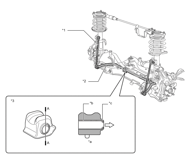
Text in Illustration *1 Front Stabilizer Link Assembly *2 Front Stabilizer Bar *3 Front Stabilizer Bar Bush - - *a A-A Cross Section *b Fluorine Coating *c Dust Lip - - Outward Direction - - Note
-
The shape of the front stabilizer bar bushes differs between the left and right sides.
-
To install the front stabilizer bar bushes on the vehicle, face their dust lips outward.
-
-
-
Suspension Tower Damper
-
The suspension tower damper consists of an ultra-low speed piston valve, gas preload cancel spring, free piston, cylinder, push rod, oil and high-pressure nitrogen gas (N2).
-
The ultra-low speed piston valve has been designed to provide damping at very low input speeds.
-
The gas preload cancel spring counters the force from the pressurized gas chamber that would otherwise press on the body in an expanding manner.
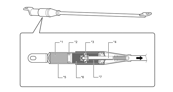
Text in Illustration *1 High-pressure Nitrogen (N2) Gas (2 MPa)
*2 Free Piston *3 Ultra-low Speed Piston Valve *4 Push Rod *5 Cylinder *6 Oil *7 Gas Preload Cancel Spring - - Gas Preload Spring Force
-
-