CRUISE CONTROL SYSTEM
-
FUNCTION OF MAIN COMPONENTS
-
The main components in the cruise control system have the following functions:
Component Function Cruise Control Switch ON-OFF Button Turns the cruise control system on and off. CANCEL Switch A cancel signal is output to the power management control ECU when this switch is operated. +RES Switch The accelerate function and resuming of a preset speed can be performed by operating this switch. A signal is output to the power management control ECU when this switch is operated. -SET Switch The decelerate function and vehicle speed setting signals are output to the power management control ECU when this switch is operated. Power Management Control ECU Controls all functions of the cruise control system in accordance with the signals from switches, sensors and ECUs. Inverter with Converter Assembly MG ECU Built into the inverter with converter assembly. Controls the motive force of hybrid vehicle transaxle assembly in accordance with signals from the power management control ECU. Hybrid Vehicle Transaxle Assembly Generates motive force for the wheels. ECM Actuates the throttle control motor in accordance with the signals from the power management control ECU. Brake Booster with Master Cylinder Skid Control ECU Transmits the VSC operation signal to the power management control ECU. Speed Sensor Detects the wheel speed of each of the 4 wheels. Combination Meter Assembly Cruise Control Indicator Light
-
Based on a cruise control indicator light operation signal sent by the power management control ECU, the combination meter assembly illuminates the cruise control indicator light when the cruise control system has been turned on using the ON-OFF button on the cruise control switch.
-
Based on a cruise control indicator light operation signal sent by the power management control ECU, the combination meter assembly turns off the cruise control indicator light if a malfunction occurs in the cruise control system.
Cruise SET Indicator Light Cruise SET indicator light illuminates when the vehicle speed is set. Multi-information Display Displays a warning message to alert the driver in accordance with a signal provided by the power management control ECU. Master Warning Light Illuminates when there is a malfunction in the system. Throttle Body Assembly Throttle Position Sensor Detects the throttle valve opening angle and outputs it to the ECM. Throttle Control Motor Adjusts the throttle valve opening angle in accordance with signals from the ECM. Stop Light Switch Detects the brake pedal being depressed and transmits its signal to the power management control ECU. Accelerator Pedal Sensor Assembly Detects the accelerator pedal depression degree and outputs it to the power management control ECU. Transmission Instrument Panel Shift Assembly Shift Lever Position Sensor Detects the shift lever position and transmits signals to the power management control ECU. Combination Switch Assembly TRC OFF Switch Detects the TRC OFF signals and outputs it to the skid control ECU. -
-
-
FUNCTION
-
The cruise control system has the following control functions.
Function Outline Constant Speed Control The power management control ECU compares the actual vehicle speed with the set speed. If the vehicle speed is higher than the set speed, the power management control ECU calculates optimal motive forces for the engine and motor generators, and decelerates by adjusting the respective motive forces. If the vehicle speed is lower than the set speed, the power management control ECU calculates optimal motive forces for the engine and motor generators, and accelerates by adjusting the respective motive forces. Set Control When this system fulfils the following conditions, and the cruise control switch is moved to the -SET side and released, the power management control ECU stores the vehicle speed and maintains the vehicle constantly at that speed.
-
The cruise control system has been turned on using the ON-OFF button on the cruise control switch.
-
The vehicle is being driven at a speed of approximately 40 km/h (25 mph) to 200 km/h (125 mph).
Low Speed Limit Control The low speed limit is the lowest speed that cruise control can be set at and it is designed to be approximately 40 km/h (25 mph). The cruise control system cannot be set below that speed. If the vehicle speed drops below that speed while the cruise control system is set and working to maintain vehicle speed, the cruise control system will be canceled automatically. However the set speed is kept in memory. COAST Switch Control When the cruise control switch is held to the -SET side, the vehicle speed and the set vehicle speed change as follows:
-
The vehicle will decelerate.
-
The set vehicle speed will change to the speed at which the vehicle is being driven when the COAST switch (-SET side operation) is released.
Tap Down Control When the cruise control switch is moved momentarily (approximately 0.6 seconds or less) to the -SET side, the vehicle speed and the set vehicle speed change as follows:
-
The vehicle will decelerate in increments of approximately 1 km/h or 1 mph each time the switch is moved.
-
However, if the difference between the actual vehicle speed and the set vehicle speed is greater than 5 km/h (3 mph), the set vehicle speed will change to the speed at which the vehicle is being driven at when the switch is ON.
ACC Switch Control When the cruise control switch is held to the +RES side, the vehicle speed and the set vehicle speed change as follows:
-
The vehicle will accelerate.
-
The set vehicle speed will change to the speed at which the vehicle is being driven when the switch is released.
Tap Up Control When the cruise control switch is moved momentarily (approximately 0.6 seconds or less) to the +RES side, the vehicle speed and the set vehicle speed change as follows:
-
The vehicle will accelerate in increments of approximately 1 km/h or 1 mph for each time the switch was moved.
-
However, if the difference between the actual vehicle speed and the set vehicle speed is greater than 5 km/h (3 mph), the set vehicle speed will not change.
RES Switch Control If cruise control speed control operation is canceled for any reason other than a malfunction (except cancelation by operating the ON-OFF button on the cruise control switch) and the vehicle speed is more than the low speed limit, the vehicle can be returned to the speed which was before the cancellation of cruise operation by moving the cruise control switch to the +RES side. The stored vehicle speed can be resumed even if the vehicle speed drops below the low speed limit, because the speed in memory has not been cleared. Manual Cancel Control If any of the following signals are sent to the power management control ECU, cruise control speed control operation is canceled accordingly.
-
Stop light switch on signal (The brake pedal is depressed)
-
Signals indicating a change in the shift state from drive (D) to another state. (The shift state is changed from drive (D) to neutral (N) or brake (B))
-
CANCEL switch on signal (The cruise control switch is moved to the CANCEL side)
-
Cruise control switch (ON-OFF button) off signal
Automatic Cancel Control If the following condition occurs during cruise control speed control operation, the speed that is set in memory is cleared and cruise control speed control operation is canceled.
-
Stop light switch open or short circuit
Furthermore, the master warning light illuminates, cruise control indicator light turns off, and a message indicating a malfunction will be displayed on the multi-information display until the cruise control system is turned off using the cruise control switch. The operation of the cruise control is disabled until the cruise control system is turned on again using the ON-OFF button.
If the following condition occurs during cruise control speed control operation, the speed that is set in memory is cleared and the cruise control is canceled.
-
Malfunction in the hybrid system
Furthermore, speed control by the cruise control system is disabled until the cruise control system is turned on again using the ON-OFF button.
If any of the following conditions occur during cruise control speed control operation, the speed that is set in memory is cleared and speed control by the cruise control is canceled.
-
Stop light switch input signal is abnormal
-
Cancel circuit malfunction
-
Brake control system malfunction
-
Communication malfunction between the skid control ECU and power management control ECU
Furthermore, the master warning light illuminates, cruise control indicator light turns off, and a message indicating a malfunction will be displayed on the multi-information display until the cruise control system is turned off using the cruise control switch. The operation of the cruise control is disabled until the power switch is turned off.
If the following condition occurs during cruise control speed control operation, the speed that is set in memory is cleared and speed control by the cruise control is canceled.
-
Vehicle speed decreases by 16 km/h (10 mph) or more below the speed at which speed control by the cruise control is set.
If the following condition occurs during cruise control speed control operation, speed control by the cruise control is canceled.
-
Vehicle speed decreases below the low speed limit (approximately 40 km/h [25 mph]).
Other Cancellation Items
-
VSC is activated.
-
TRC is activated for a period of time.
-
When the TRC system is turned off by pressing the TRC OFF switch.
-
-
-
CONSTRUCTION
-
Cruise Control Switch
-
The cruise control switch consists of the ON-OFF button and the +RES, -SET and CANCEL switches. The +RES, -SET and CANCEL switches are operated by moving the lever in the 3 directions indicated.
-
The switches in the cruise control switch are of the an automatic reset (normally open) type that turn on only when the switch is being operated and turn off as soon as the driver releases the switch. Furthermore, the functions of the switches are active only when the cruise control system has been turned on using the ON-OFF button on the cruise control switch.
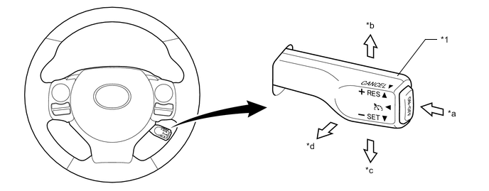
*1 Cruise Control Switch - - *a ON-OFF Button *b +RES Switch *c -SET Switch *d CANCEL Switch
-
-
-
OPERATION
-
Combination Meter Assembly
-
The combination meter assembly has a master warning light, cruise control indicator light, cruise SET indicator light, buzzer, and multi-information display to provide warnings and messages regarding the cruise control system.
-
The multi-information display displays the set vehicle and warning message.
-
Examples are shown below for the illumination or display of each indicator light, warning light or multi-information display.
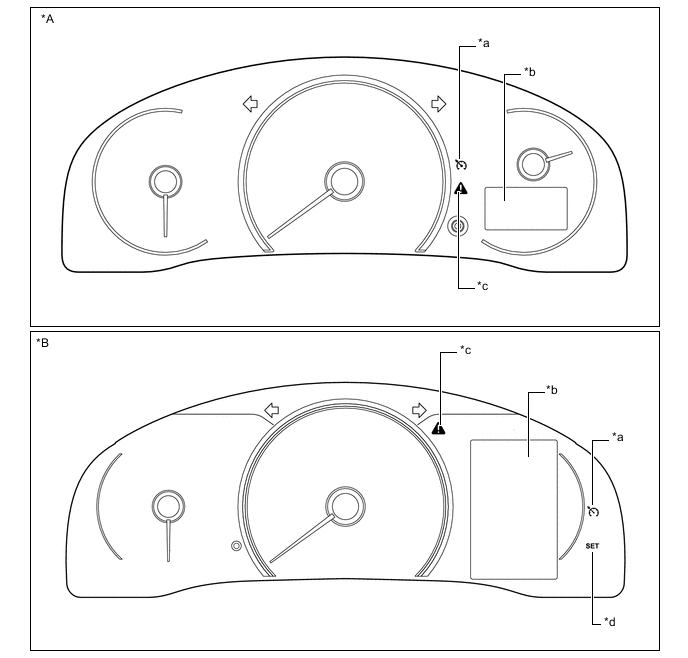
*A Models with Monochrome Type Multi-information Display *B Models with Color Type Multi-information Display *a Cruise Control Indicator Light *b Multi-information Display *c Master Warning Light *d Cruise SET indicator Light Models with Monochrome Type Multi-information Display Condition Multi-information Display*1, *2 


Buzzer Being Controlled 
Does not illuminate Illuminates Illuminates*3 - System Check CHECK CRUISE CONTROL SYSTEM Illuminates Does not illuminate Does not illuminate Sounds *1: While driving at a set speed of 100 km/h (62 mph).
*2: These illustrations are examples.
*3: Message displayed on the multi-information display.
Models with Color Type Multi-information Display Condition Multi-information Display*1, *2 Buzzer Being Controlled 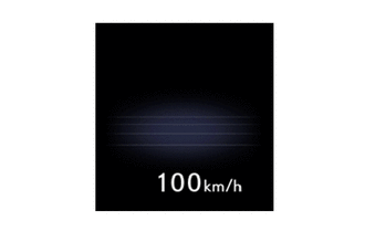
Does not illuminate Illuminates Illuminates - System Check Cruise Control Malfunction Visit Your Dealer Illuminates Does not illuminate Does not illuminate sounds *1: While driving at a set speed of 100 km/h (62 mph).
*2: These illustrations are examples.
-
-
-
DIAGNOSIS
-
If a malfunction occurs in the cruise control system during cruise control operation, the power management control ECU automatically cancels the cruise control, illuminates the master warning light, sounds a buzzer in the combination meter assembly, and displays a warning message on the multi-information display to inform the driver of the malfunction. At this time, the power management control ECU memorizes the malfunction in the form of a Diagnostic Trouble Codes (DTCs).
-
The DTCs can be read when a Global TechStream (GTS) is connected to the DLC3. For details, refer to the Repair Manual.
-