LUBRICATION SYSTEM
-
CONSTRUCTION
-
Oil Pump
-
A gear-type oil pump is used.
-
The oil pump and the vacuum pump are integrated as one unit.
-
A pressure limiting valve is located in the oil pump. The pressure limiting valve limits the oil pressure to a maximum permissible level.
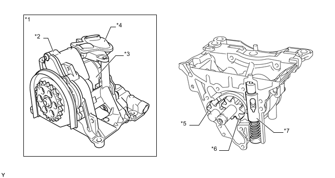
Text in Illustration *1 Oil Pump with Vacuum Pump Assembly *2 Oil Pump *3 Vacuum Pump *4 Oil Strainer Sub-assembly *5 Oil Pump Driven Gear *6 Oil Pump Drive Gear *7 Pressure Limiting Valve - -
-
-
Oil Filter Assembly
-
General
-
The oil filter assembly consists of an oil filter housing, a filter bypass valve, an oil filter element, a non-return valve, an oil cooler bypass valve, an oil cooler and a drain valve.
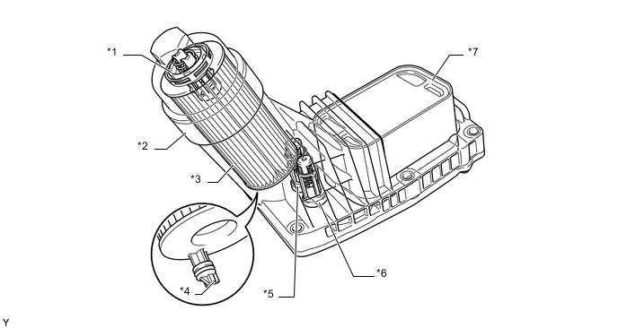
Text in Illustration *1 Filter Bypass Valve *2 Oil Filter Housing *3 Oil Filter Element *4 Drain Valve *5 Non-return Valve *6 Oil Cooler Bypass Valve *7 Oil Cooler - - -
-
Filter Bypass Valve
-
When the difference in pressure before and after the filter exceeds the predetermined pressure while the filter is blocked or while it is difficult for oil to pass through the filter due to low engine oil temperature and high oil viscosity, the filter bypass valve opens and the engine oil bypasses the filter.
-
-
Oil Cooler Bypass Valve
-
When the oil pressure exceeds the predetermined pressure due to low engine oil temperature and high oil viscosity, the oil cooler bypass valve opens and the engine oil bypasses the oil cooler.
-
-
Non-return Valve
-
This valve prevents engine oil from returning from the oil filter when the engine has been stopped and prevents the filter from drying up. As a result, the supply of engine oil during engine restarts has been secured.
-
-
Drain Valve
-
When the filter is changed, the oil flows from the drain valve into a return duct and back to the oil pan sub-assembly. A plunger with a seal is located on the bottom of the oil filter element and seals the return line when the filter cap is closed. When the oil filter cap is opened for an oil change, the oil filter element attached to the oil filter cap also moves upward. The plunger with the seal is withdrawn from the return duct and the oil flows to the oil pan sub-assembly. The drain valve is integrated into the oil filter and is thus changed when the oil filter is replaced.
-
-
Oil Cooler
-
The oil cooler utilizes the temperature of the engine coolant to quickly heat up the engine oil while the engine warms up and then afterwards efficiently cools the oil.
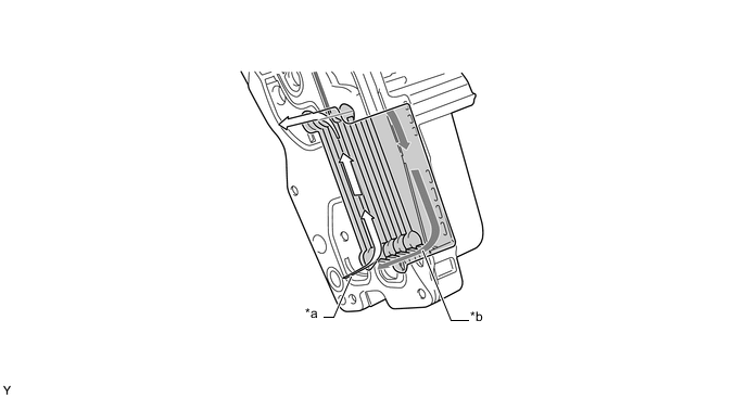
Text in Illustration *a Oil Flow *b Coolant Flow -
-
-
No. 1 Oil Nozzle Sub-assembly
-
No. 1 oil nozzle sub-assembly is provided in the cylinder block sub-assembly for cooling and lubricating the pistons.
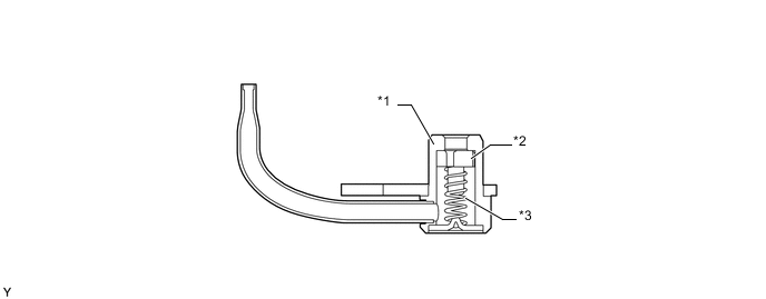
Text in Illustration *1 Housing *2 Valve *3 Compression Spring - -
-
-
-
OPERATION
-
Oil Pump
-
Gear-type Oil Pump
-
In this oil pump, 2 gears with external teeth mesh with each other (one gear is driven). The crowns of the teeth not in use move along the pump housing, delivering engine oil from the suction chamber to the pressure chamber.
-
The residual oil quantity remaining in the tooth gullet (pressurized oil) may cause a problem because it can reach very high pressures. That is why relief grooves are incorporated in the pump housing and cover to divert the pressurized oil into the pressure chamber.
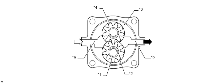
Text in Illustration *1 Drive Shaft *2 Gear (Oil Pump Drive Gear) *3 Oil Pump Housing *4 Gear (Oil Pump Driven Gear) *a Suction Chamber *b Pressure Chamber 
Engine Oil (Low Pressure) 
Engine Oil (High Pressure)
-
-
Pressure Limiting Valve
-
The engine oil pressurized by the oil pump is sent to the pressure chamber.
-
Some engine oil in the pressure chamber is supplied to the upper control chamber on the upper side of the pressure limiting valve. The rest of the engine oil is sent to the oil filter. The engine oil which has passed through the oil filter is sent to the main oil gallery and returns to the oil pump housing. Then, the oil passes through the bore and is supplied to the lower control chamber on the lower side of the pressure limiting valve. As a result, the oil pressure between the oil filter and the oil pump is applied to the upper control chamber. The oil pressure (system pressure) in the oil circuit after the oil filter is applied to the lower control chamber. The control plunger is pushed toward the control chamber side by the compression spring.
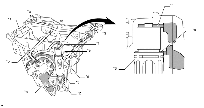
Text in Illustration *1 Oil Pump *2 Compression Spring *3 Control Plunger - - *a To Oil Filter *b Pressure Chamber *c Suction Chamber *d Bore *e Lower Control Chamber *f Upper Control Chamber *g From Main Oil Gallery - - -
The pressure limiting valve is closed when the oil pressure is low.
-
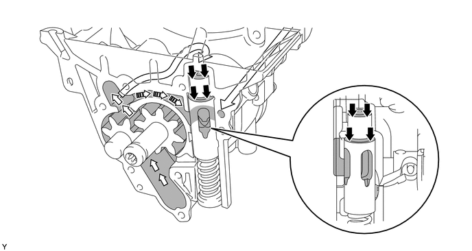
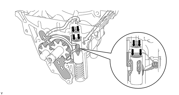
When the system pressure increases and becomes larger than the compression spring force, the control plunger is pushed by the oil pressure to open the passage leading from the compression chamber to the suction chamber. As a result, the system pressure is reduced.
Tech Tips
When the oil filter is blocked, the oil pressure before the oil filter (oil pressure in the upper control chamber) increases. However, the system oil pressure after the oil filter (oil pressure in the lower control chamber) does not increase. When the pressure limiting valve is controlled using the oil pressure before the oil filter, a lack of lubrication may occur. Also, when the engine oil temperature is low and the oil viscosity is high, the system oil pressure may become too high and cause damage to the components. To prevent damage to the components, the oil pressure before the oil filter (oil pressure in the upper control chamber) and the system pressure after the oil filter (oil pressure in the lower control chamber) are both utilized to control the pressure limiting valve.
-
-
-